Posted on Leave a comment

A Super Versatile Minotaur, Rigged And Ready To Rumble

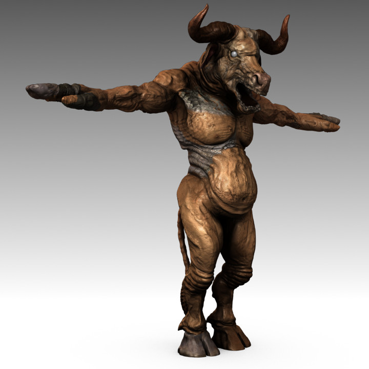
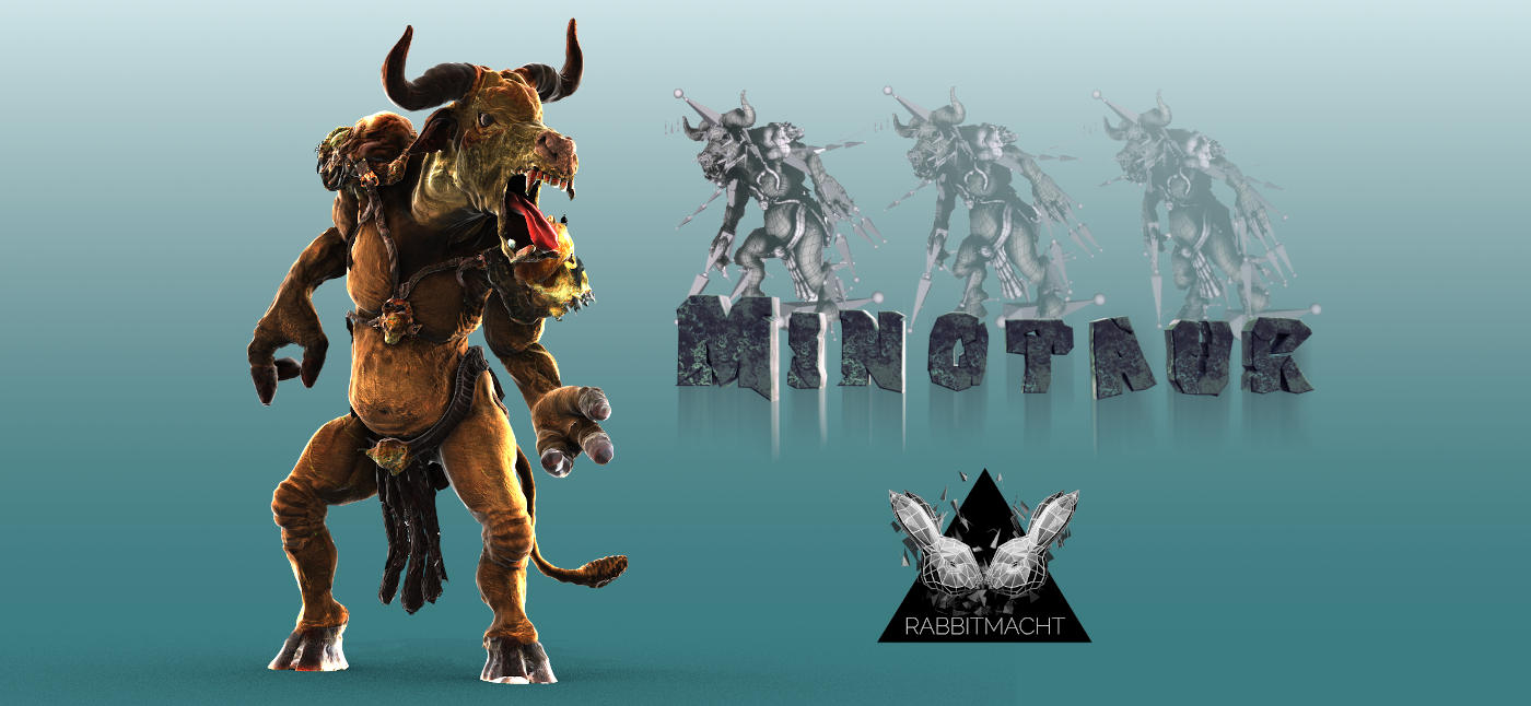
Lets dive into the details on the Minotaur character that has recently been published by RABBITMACHT.

In this post, we are focusing on how you can incorporate The Minotaur 3D Digital Asset into your own projects by exploring how this character is built and effectively leveraging these resources in your own workflow.

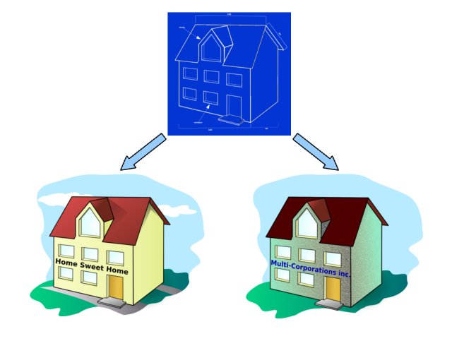
The Minotaur consists of two main 3D components that being the Minotaur itself and the Minotaur’s Armour. As the components are modelled separately they are not interdependent. In other words, you can use the Minotaur with or without his armour and/or extract and use the armour on a completely separate character.

Although these two components also consist of other objects or sub-components, what distinguishes these main components is that each sub-component inhabits the same UV layout within its main component.

Let’s have a look at the main components in a little more detail.

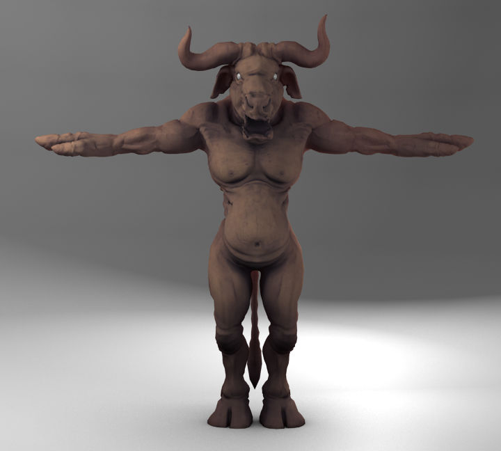
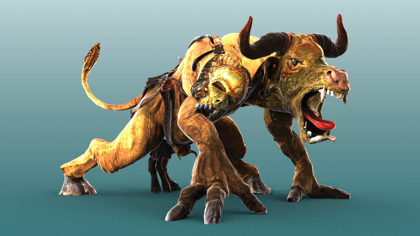
Main Component 1 : The Minotaur Model

The Minotaur Model can further be broken down into several other components including

  • upper teeth and lower teeth
  • tongue
  • left eye and right eyes

As these components typically do not deform during animation (they are only transformed), they can safely be parented to a bone for the purposes of animation.

This is, of course, with the exception of the tongue. As the Minotaur uses Blender’s Rigify system, we fortunately are provided with deformation bones and controllers too for the tongue.

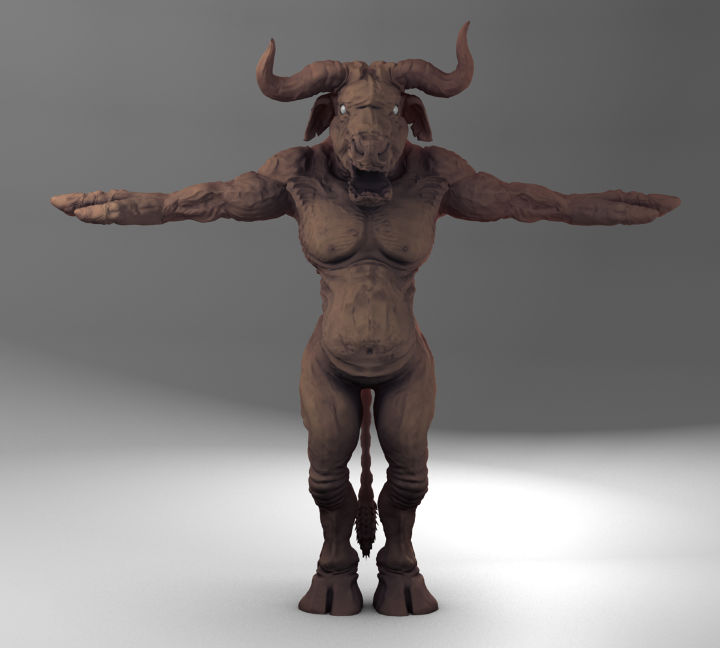
Main Component 2 : The Minotaur’s Armour

The Armour is a more complex main component as it is made up of several objects. Including,

  • Straps
  • Shoulder Guards
  • Loincloth

How these components contribute to the rig during animation, takes on three different approaches.

The simplest approach can be seen with the shoulder guards which are weighted to the Minotaur’s shoulder bones and also to the first upper arm bone for a little extra deformation that assists with the prevention of objects intersecting.

Avoiding Intersections

It’s worth noting at this point that in order to rig the Armour so that it deforms with the Minotaur’s movements and avoids excessive intersections, we have taken a hybrid approach that results in a combination of techniques while keeping viewport interactivity responsive with minimal dynamic simulations.

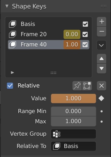
Bearing this in mind although the straps could be animated with a cloth simulation, this would be overkill given that they are intentionally designed to look and act like a hard leathery material. As a result, the straps are weighted to the armature and follow the Minotaur’s body deformations. One of the key tools, in terms of avoiding too many intersections between the Armour straps and the Minotaur’s body, would be in Shape Keys. Shape Keys or Morph targets can be used to tweak the armour and main body when intersections become visible.

Shape Keys are particularly useful when rendering stills as they add a great deal of convenience, without compromising on the outcome or the scene’s believability.

Finally, the Minotaur’s loincloth is animated by means of dynamic simulation. This adds to the scene’s realism while keeping simulations at a minimal. The Minotaur’s body is set as a collision object and as both objects have a polycount that can be rendered in realtime the simulation can be computed within a very reasonable timeframe.

As a result it’s advisable that you Bake a dynamic simulation to disk before rendering an animation

What does the Minotaur product consist of?

The Minotaur product comes with two main production-ready blend files, a supplementary FBX file with a baked walk cycle and a water-tight, stylized STL file for 3D printing.

  • Minotaur_for _animation
  • Minotaur_for_stills
  • FBX baked walk cycle
  • STL stylized model for 3D printing

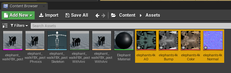
Each file is optimized for it’s specified outcome and the production-ready blend files all have textures in high-res, 4K packed into the .blend file.

Production-Ready Files

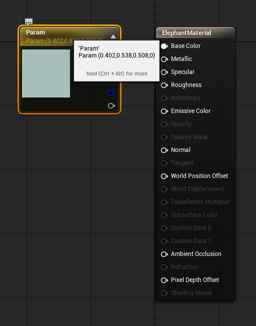
The Minotaur for Animation file uses Blender’s Eevee renderer with the Principled BSDF shader. This provides the speed and level of detail required to render animation sequences with reasonable overhead and quality.

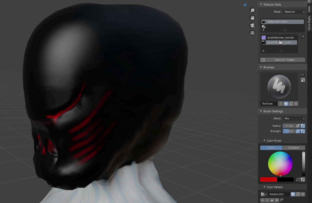
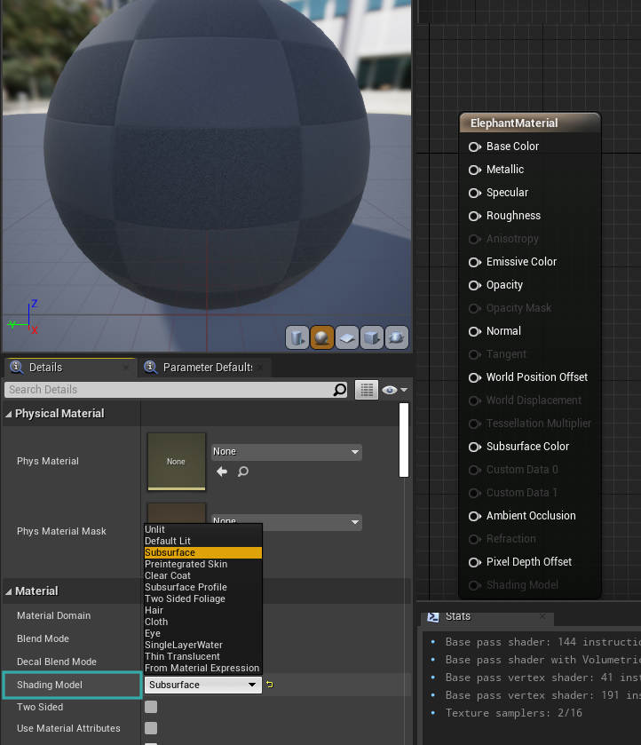
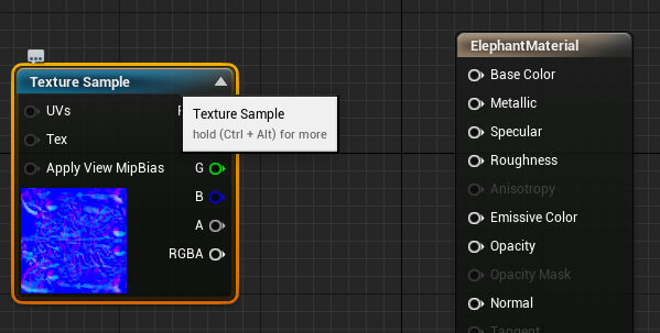
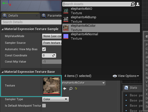
The Minotaur for stills file uses a more complex approach to rendering by leveraging on Blender’s Cycles renderer. Both the main Minotaur and Armour meshes have highly customizable shading networks that include Sub-surface scattering (SSS), Fresnel, Ambient Occlusion and many high-res masks for targeting specific parts of each model. For instance, if you wanted to change the minotaur’s veins from green to red and make them glow there are already masks in place to help you achieve that.
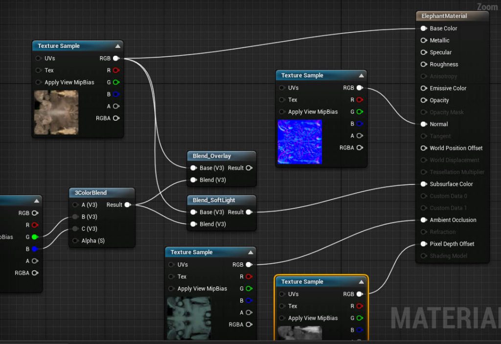
Shading Network

Although at first glance the Shading Network might seem complicated, it is in fact very logical and follows a simple design principle. That being,

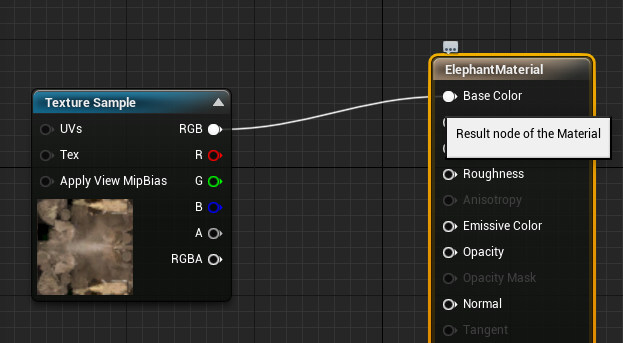
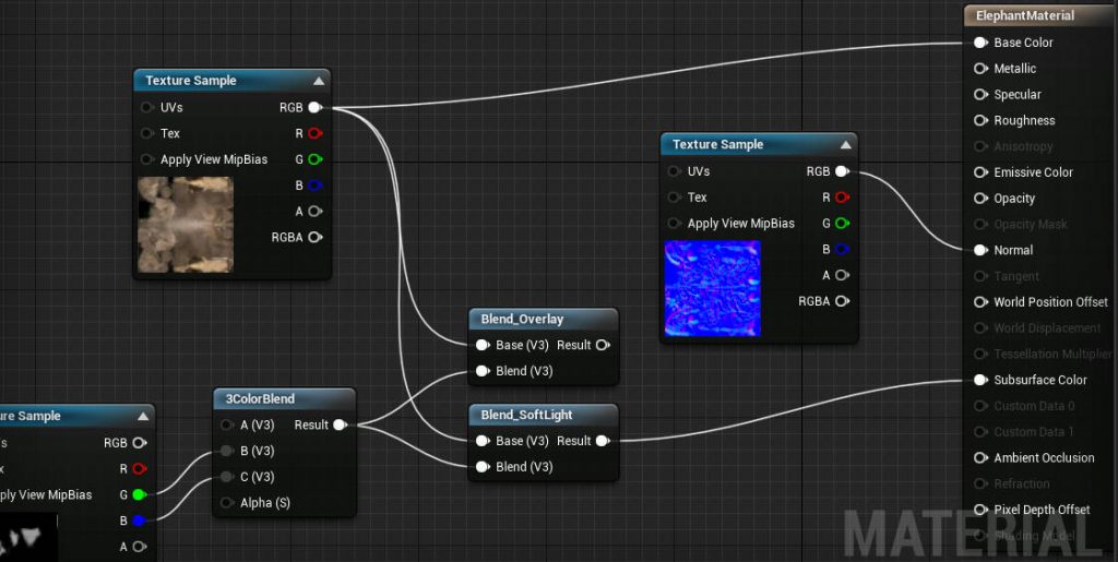
Create a single shader (for example a Diffuse) that applies to the entire model.

Then minimize the shader’s coverage with a mask and mix in the previous shader that followed the same methodology, through a Mix shader.

Effectively, what this means is that it is really easy to take each Shader’s output and plug it directly into the Material Output’s Surface input to see exactly how each shader affects the model.

If you would like to learn more about how the textures, materials and UV’s are built for the Minotaur, the following post can help you gain deeper insight.

This post covers SSS and the differences in Render Quality based on a conventional setup vs the minotaur’s proprietary setup

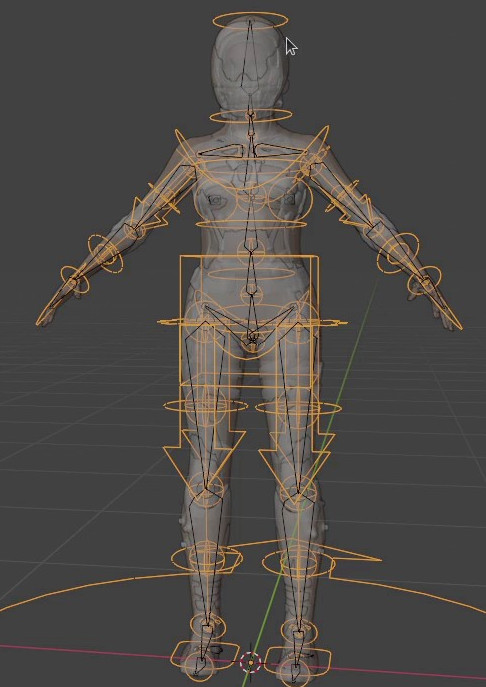
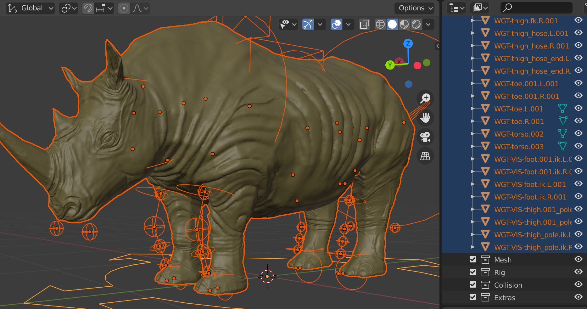
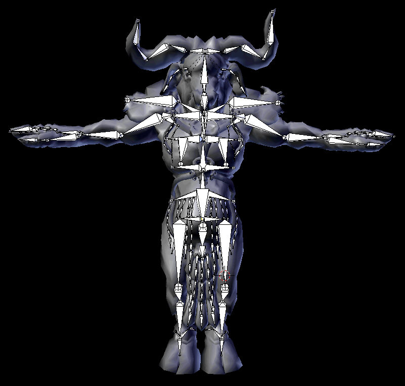
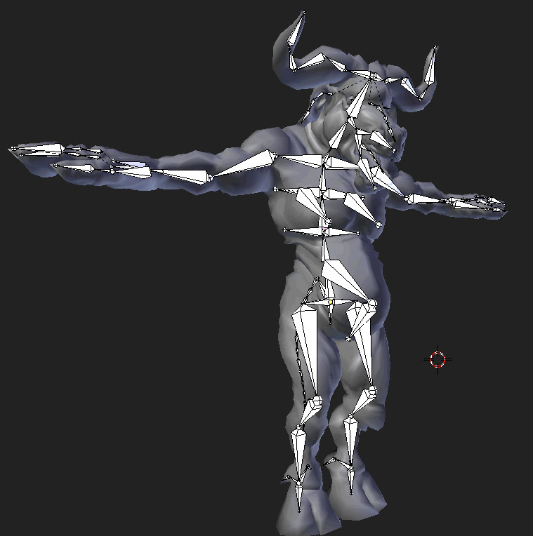
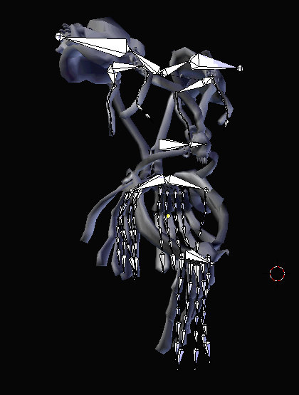
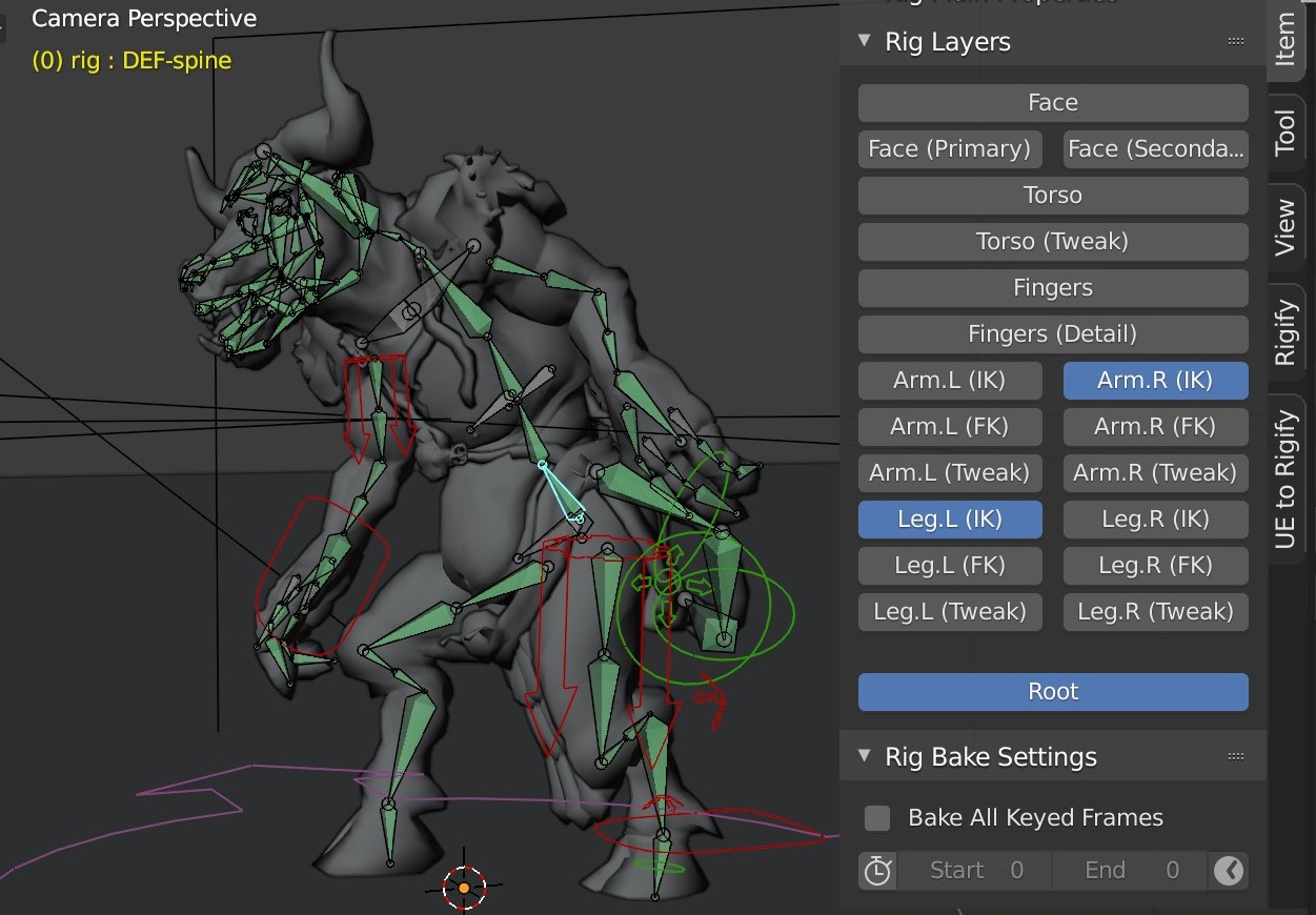
Rigged with Rigify for Animation

Although I have often noted the benefits of a translation-biased rig to many of my students, in this instance, for the sake of simplicity and to curb the learning curve the Minotaur uses the very popular Rigify for animation. As you may already be aware Rigify automates the process of creating a Forward Kinematics (FK) rig which is used for deformation as well as a controller rig that uses various transforms and restraints for posing the FK rig.

Animating with Rigify is intended to be relatively straight-forward and once your animation rig has been generated no special plugins are required thereafter.

The Rigify Metarig has also been included in the production files, giving you the ability to regenerate the rig if you wish to do so.

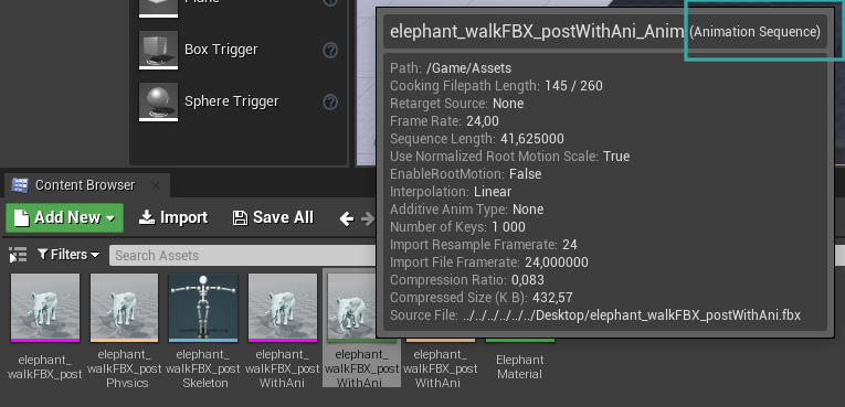
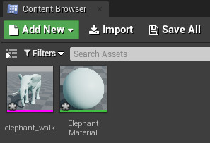
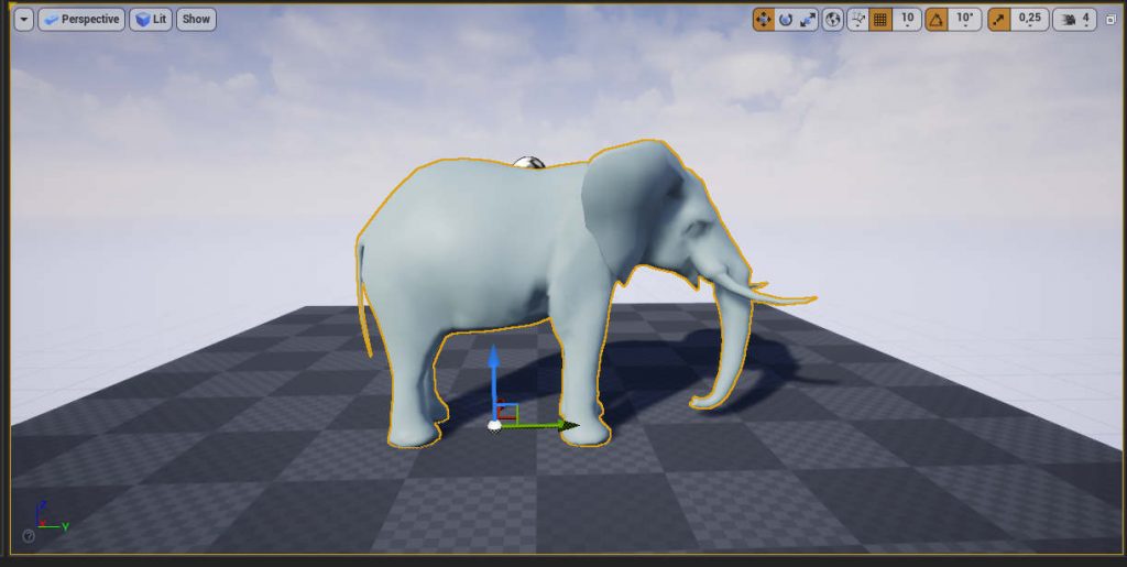
The minotaur comes equipped with a 40 frame loopable walk cycle. This provides an example of how you would set up multiple animations for your character particularly if you wanted to export it to a game engine.

If you want to learn more about the significance of a Forward Kinematics rig the following post can help you get a better understanding of that. Although controller rigs are essential for making character animation manageable and will generally consist of various hierarchical chains with restraints such as Inverse Kinematics, they will still typically rely on an underlying FK rig to actually deform your character’s geometry, read more below..

In this post we take a closer look at a custom FK rig for the Minotaur and his armour

Using the NLA Editor

Blender’s Non-linear Animation Editor, not to be confused with an NLE (Non-linear Editor) which is typically used for video editing and is also another tool available within Blender, provides a high level of abstraction relating to animation data. In much the same way that you can rearrange video clips in an NLE such as Adobe Premiere Software, Blender’s NLA Editor allows you to convert animation sequences into clips (also called Actions) and rearrange them in any desired order.

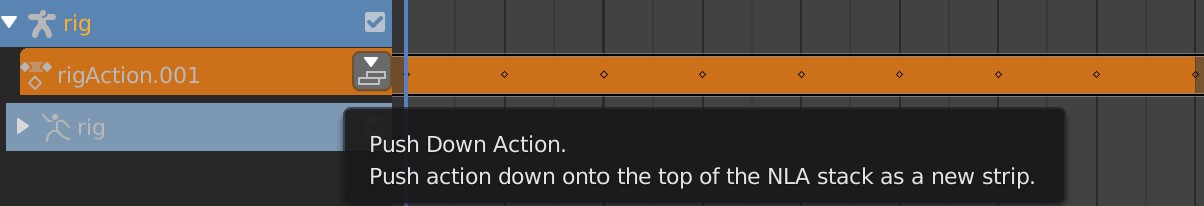
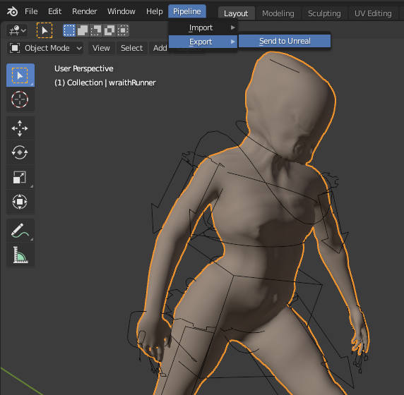
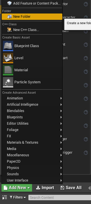
With the rig selected open Blender’s Non-Linear Animation (NLA) Editor. This allows you to push down the current animation to an Action. When exporting animations for a game character you would typically create multiple Actions such as walk, run, jump etc. By using actions the game engine is able to distinguish one sequence from another in a non-linear way. In other words, if you wanted your character to jump the game engine would go straight to the jump action as opposed to first playing the walk animation then the run animation and finally reaching the jump animation.

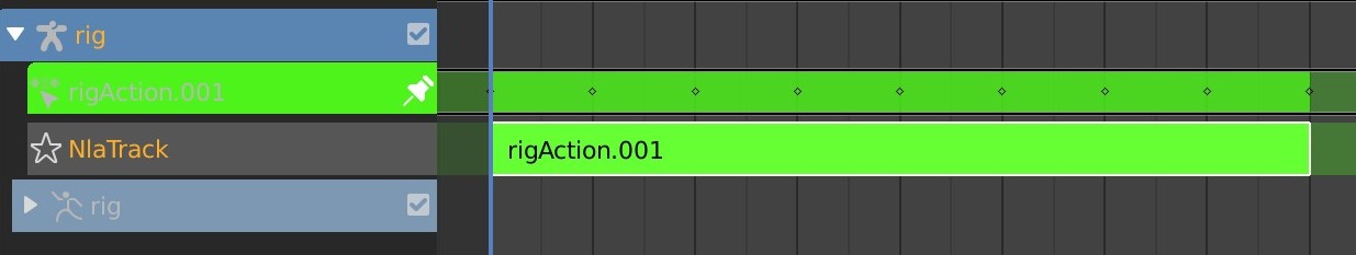
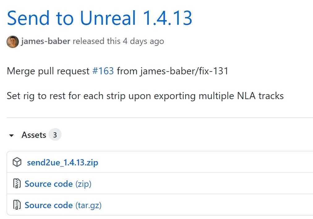
Once an Action has been created you can still edit it by simply selecting the action in the NLA Editor and hitting Tab on the keyboard. The action’s keyframes will then be exposed in the Timeline, Graph Editor and the Dope Sheet. To create another Action you could return to the NLA select the action you are editing and hit Tab to exit Edit mode. Then simply keyframe another animation. To ensure that the old action does not override the visibility of the new action uncheck it’s NLA track, this effectively mutes the action.

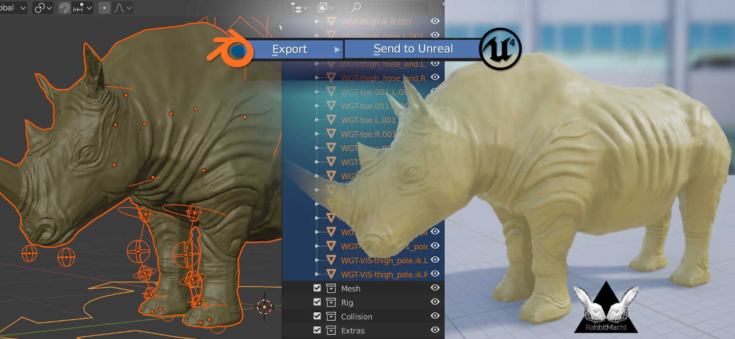
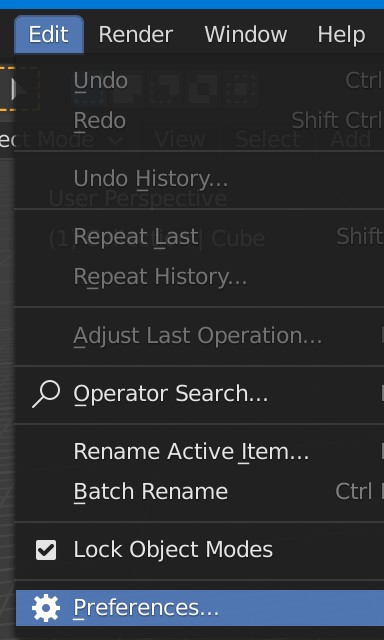
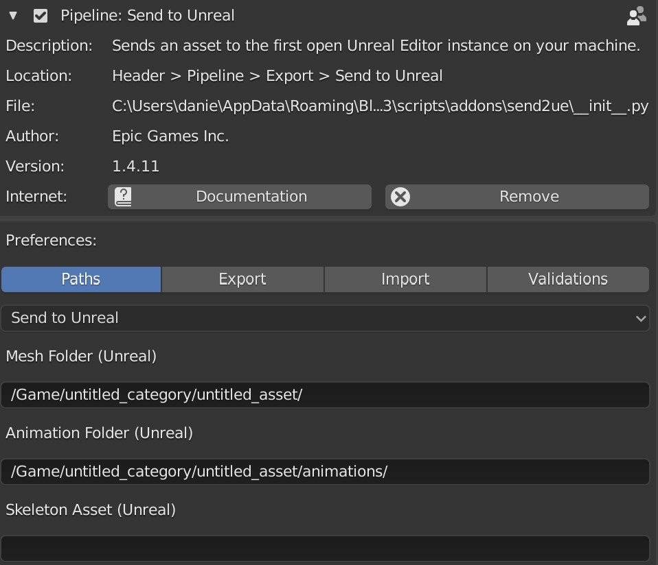
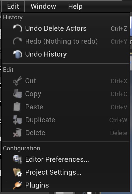
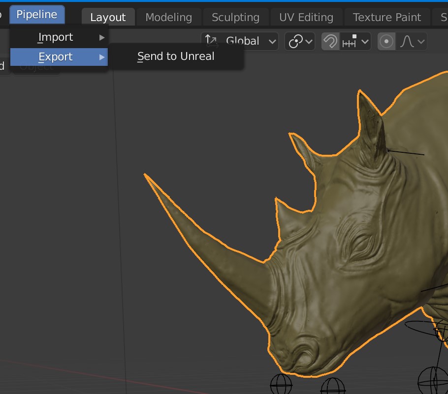
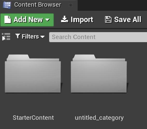
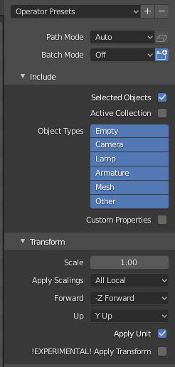
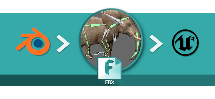
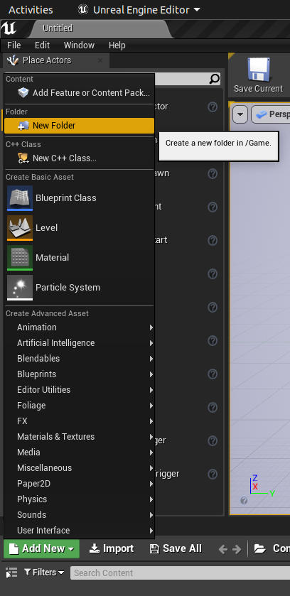
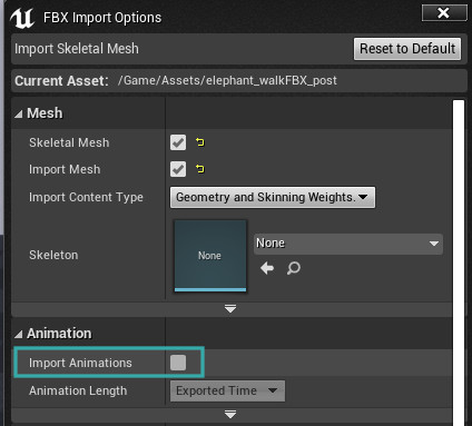
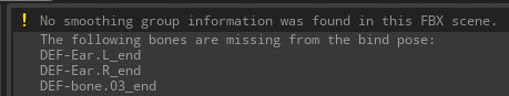
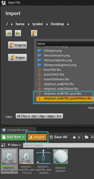
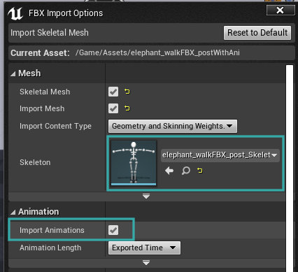
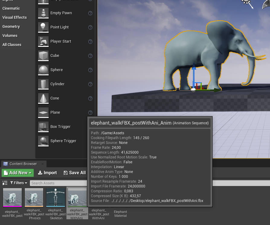
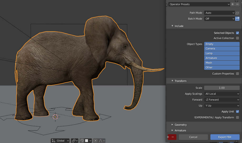
Also included within the Minotaur product is an FBX file demonstrating what an animation baked and exported might look like. You can simply import this FBX into another 3D application or separate it into two main parts one consisting of the rig with the Minotaur and the other consisting of the rig with the Armour. There are many different ways of exporting animations from Blender into game engines including UE to Rigify and UEfy to name a few. However, your use case might require something different. If you have any questions, comment below and someone will be sure to help you out.

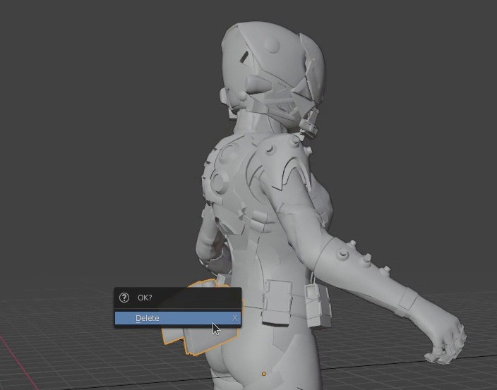
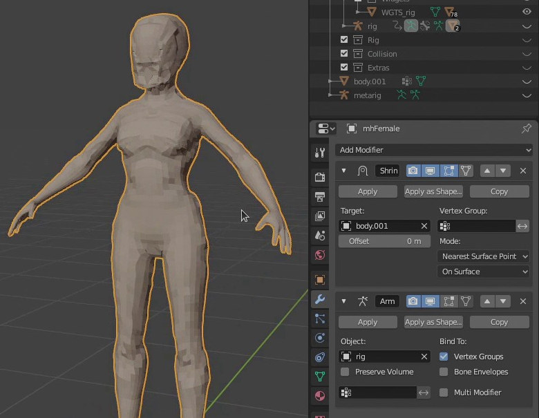
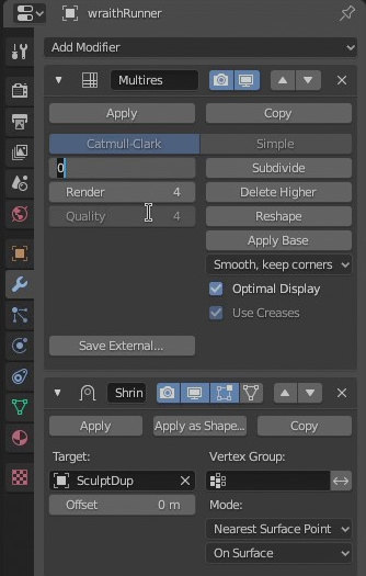
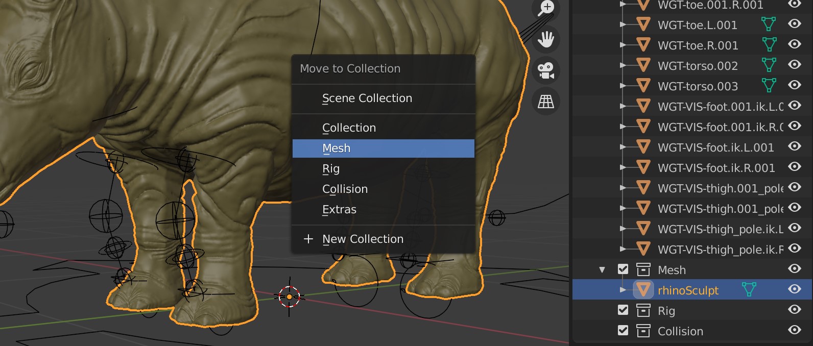
Working with Proxies and the Shrinkwrap modifier

The Minotaur comes with an active Modifier stack, this means that in order to get the most out of the file it’s recommended that the file is edited in Blender. The modifier stack actively contributes to the file’s output, it is editable and some components are hierarchically immutable. Understanding the Minotaur’s proxy model setup will assist greatly in reconfiguring the modifier stack.

Find out more about the Minotaur’s modifier stack and how it optimizes the rendering process, both in the viewport and for high quality renders, by means of proxies in the following posts.

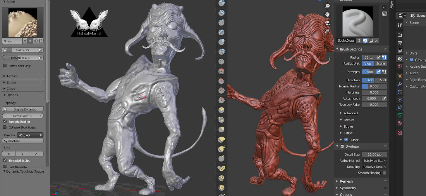
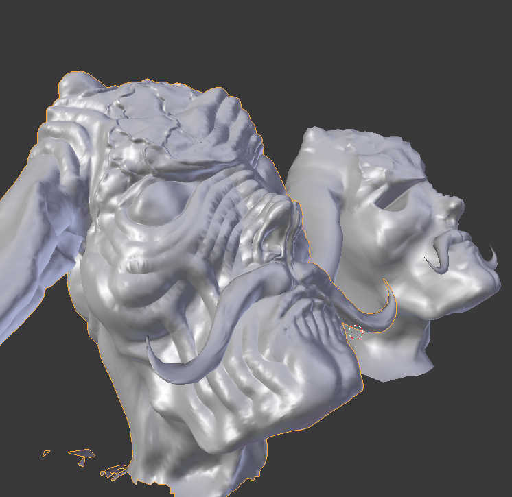
High Resolution Sculpt Data

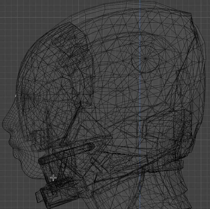
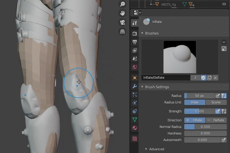
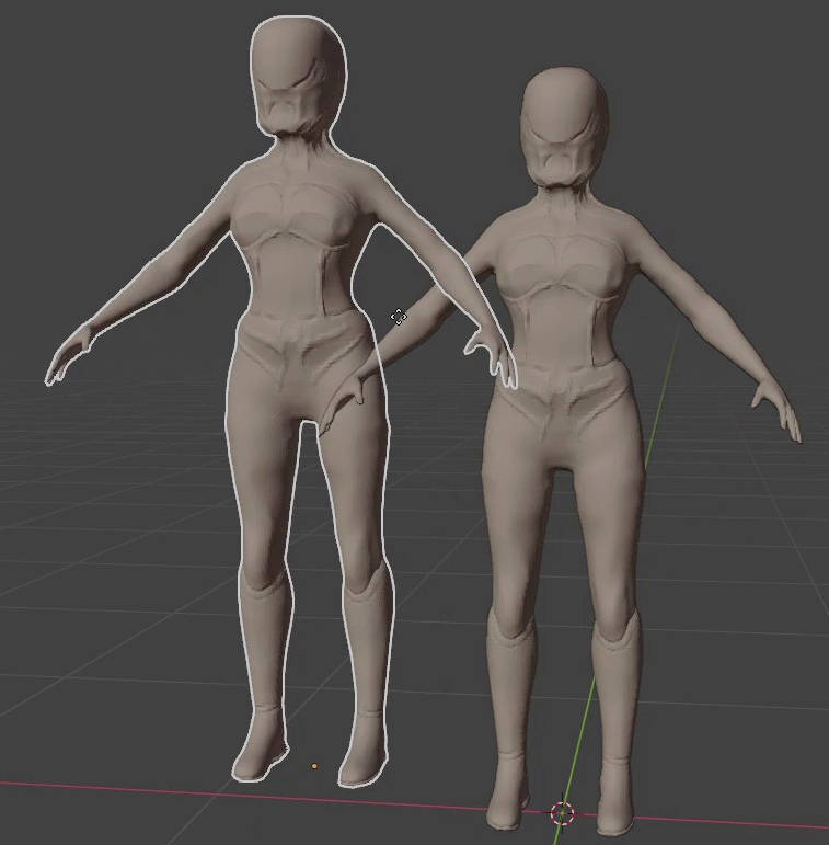
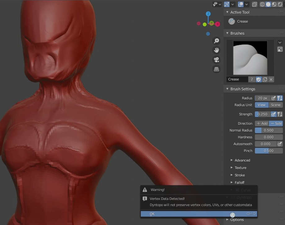
The Minotaur for stills file comes with an ultra-high-resolution sculpted version of the Minotaur and his Armour. You can find the high-res versions within a scene collection post-fixed with HR. These models are made of many hundreds of thousands of polygons so caution should be exercised when trying to render these models.

Their primary purpose is for the displacement of the realtime model’s subdivisions through the Multires modifier at render-time.

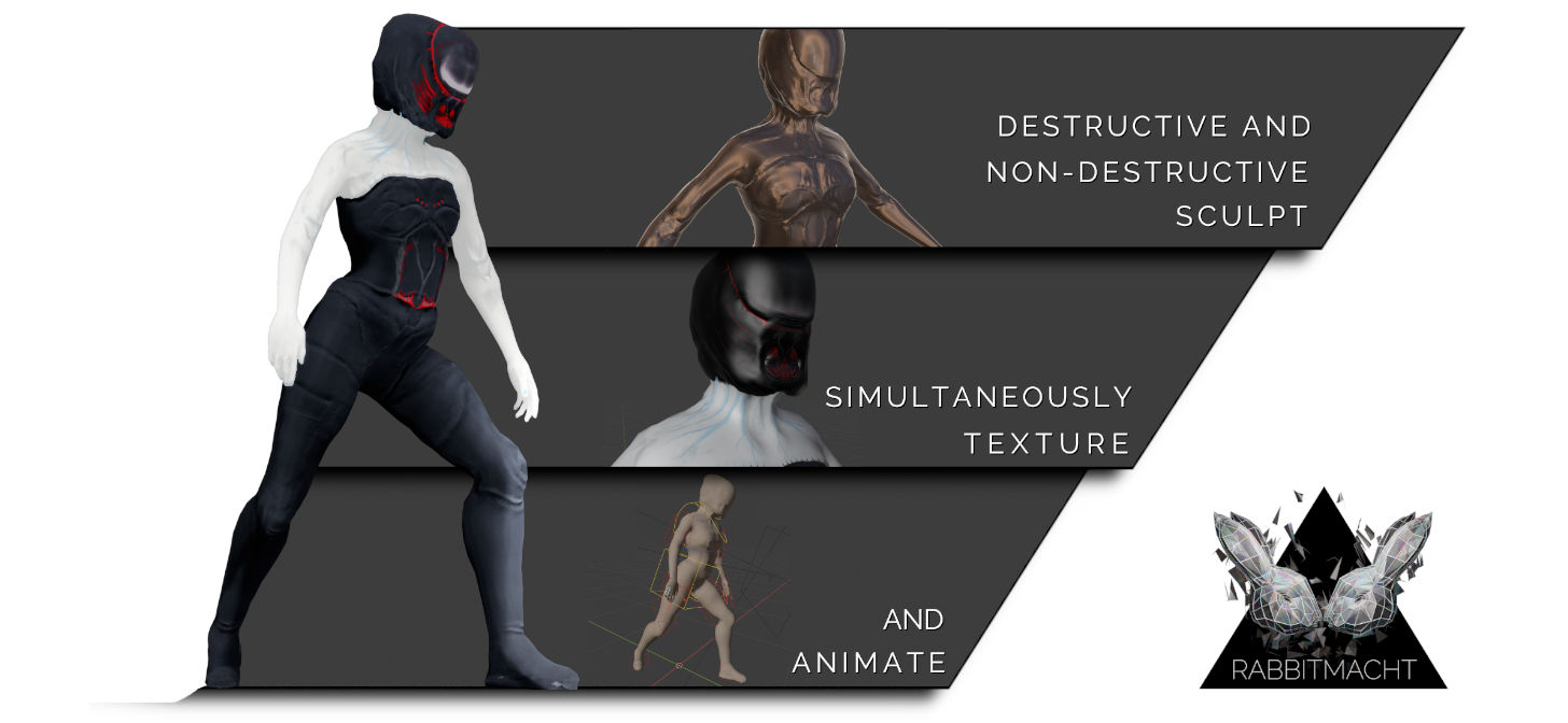
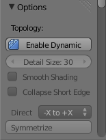
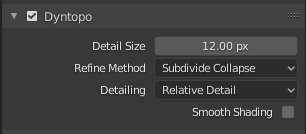
In the following post, you can find out more about how the high-res models are constructed through non-destructive as well as Dyntopo sculpting.

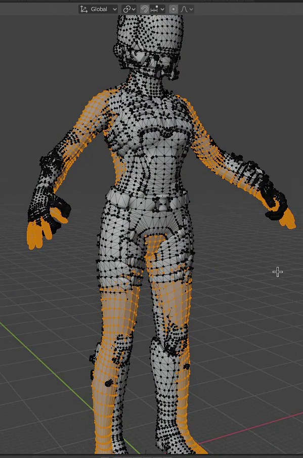
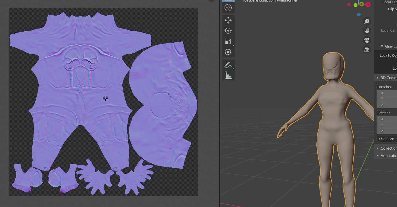
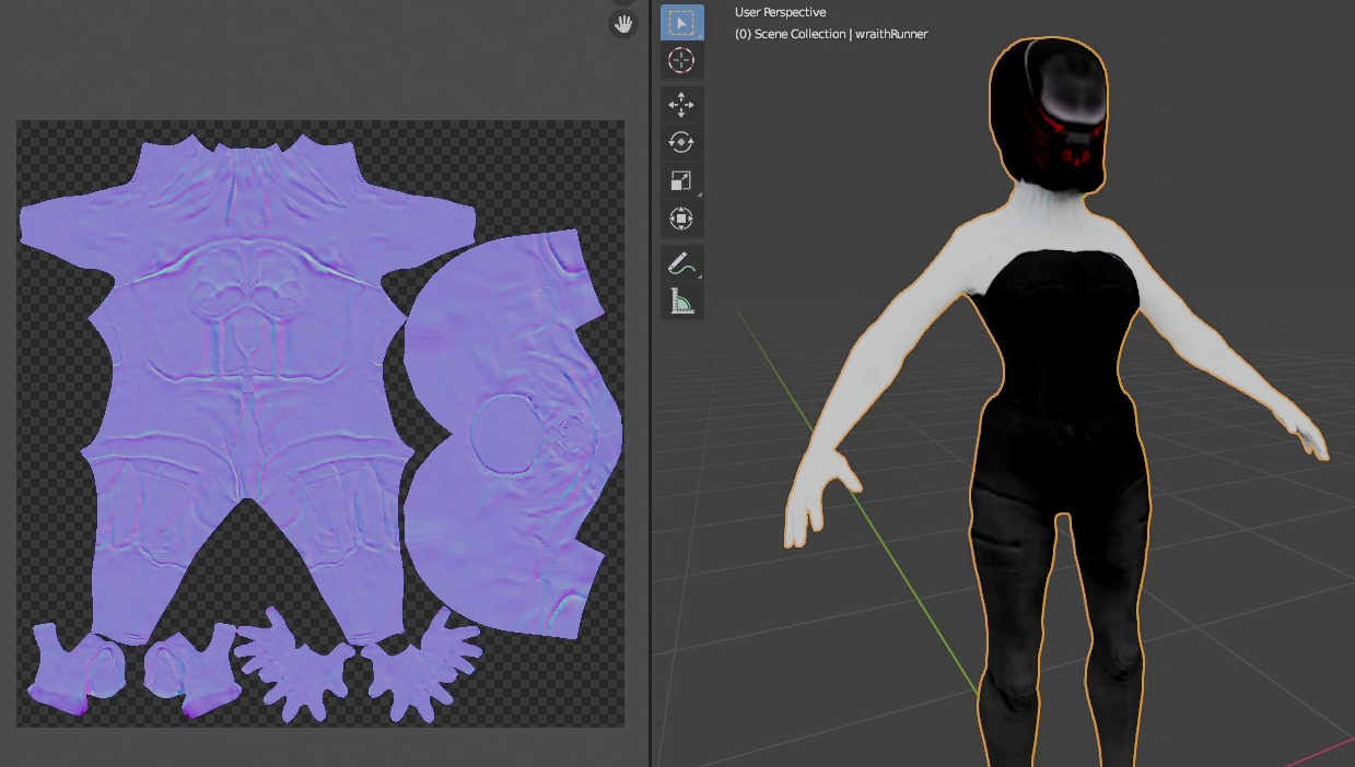
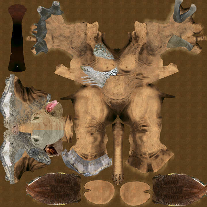
A Highly Efficient UV Layout

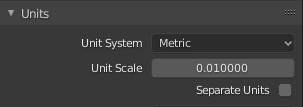
Whether you are creating characters that will be hand painted or texture mapped by compositing photos an efficient UV layout is crucial to avoid exposing seams. A UV layout that is effective will not only be applicable for your 3D application but for 2D editing as well, as such UV’s should be laid out matching the form of a character as close as possible while still avoiding stretching.

You can find out more about generating an efficient UV layout in the following post.

Where can I get the Minotaur?

The Minotaur is available from the RABBITMACHT store for direct purchase. This comes with a great deal of product support and all minor updates are free.

The Minotaur comes with a standard Royalty-free license, which gives you as much versatility as you can possibly need to use it in your own projects including both commercial and non-commercial, educational or other.

You can also get your copy of the Minotaur from RABBITMACHT’s Blender Market store.

If you have any questions leave a comment below or get in touch. We’d love to hear from you.

Subscribe To RabbitMacht

Get new posts delivered to your inbox

* indicates required
/ ( mm / dd )
Posted on Leave a comment

How To Build Game-ready Characters With A Non-destructive Workflow

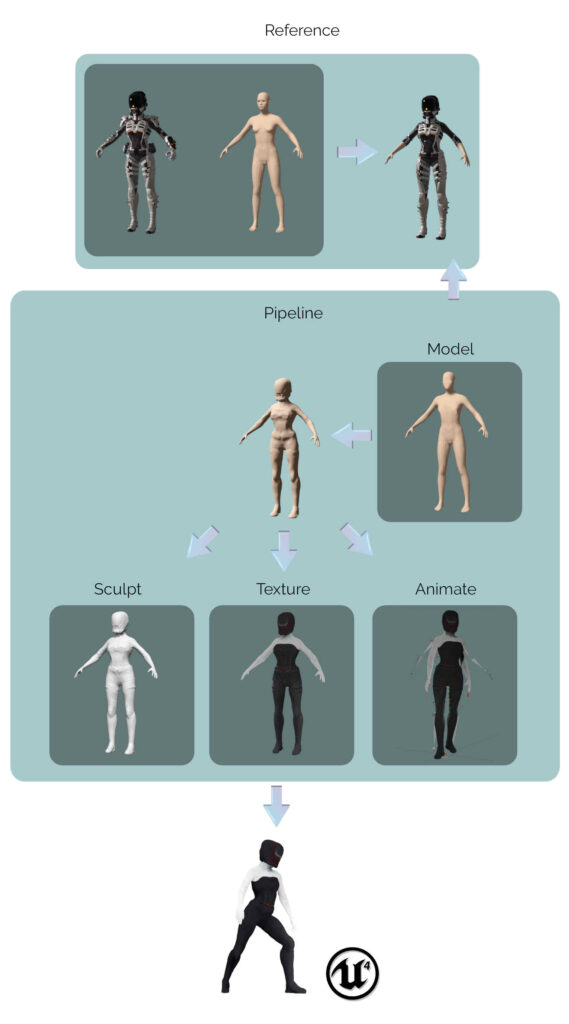
When developing 3D characters it’s important to retain as much of a non-destructive workflow as possible.

This is particularly important with regards to games development as the models used in the final output will often have certain elements baked into texture maps.

Without a non-destructive workflow, modifying a baked a texture map or rebuilding components of your character might be your only option when making changes to your final output becomes necessary. It can be particularly difficult to achieve your desired results as it requires a very indirect approach to editing, thereby compromising on control, detail and taking up more time than necessary.


A non-destructive workflow means retaining as much of the character’s creation history as possible. This means that reverting to different stages in your character’s creation process becomes a lot more accessible. You can then make the changes where necessary (be it at the modelling, texturing, sculpting, rigging or other stages) and automatically allow those changes to propagate throughout your character’s production pipeline.

Although setting up characters in this way might require a bit more planning, initially, once you get into the hang of it and start seeing the benefits of how much time it can save you in the long-run the technique will soon become a necessity in your character development toolkit.

Setting up a reference

Starting with references is typically advisable. They could either be 2D images or, as in this case, we are using a 3D model of a wraith-like-character.

Cleaning the reference

This reference model will not be used in the final output as it simply forms the starting point within the modelling process. This reference model also consists of a great deal of non-manifold geometry which would make attaching it to an armature unpredictable.

As the character we are building is designed to be more streamlined and agile we will not need a lot of the accessories attached to this model.

With the reference model selected simply,

  • Go into Edit mode,
  • Select a single vertex from the model’s component you want to delete.
  • Hovering over the 3D Viewport, hit L on the keyboard
  • and Blender will select all connected vertices.

This makes deleting whole portions of the model much easier.


MakeHuman is an open-source application for generating human-like 3D characters.

Primarily we use MakeHuman as it gives us a base mesh with edge loops that deform really well during animation and an efficiently laid out UV map that maximizes on 0 to 1 texture space.

The MakeHuman model is then exported as an OBJ file and imported into Blender. The OBJ file format has the added bonus of retaining a model’s UV layout.

Line the MakeHuman model up with the reference model. When modifying the models, avoid transforming the models at the object level. In other words, when scaling the model to match your game engine’s units do so in Edit mode. Select and scale the model’s vertices towards that of the reference model. This ensures that translations and rotations for the game model remain at 0 while scale for all axes remains at 1. This results in more predictable, in-game behaviour for your assets.

When creating content for the Unreal Engine you should ensure that your scene units are set to metric with a value of 0.01

It’s worth pointing out that currently, we are setting up the reference model. The previous image depicts the reference model with its original arms removed and replaced with the make human models lower arms and hands. The original model has also had half of it deleted then mirrored on the remaining half.

This symmetrical modelling technique is not advised for the model that will be exported to UE4 as it will result in overlapping UV’s. However since we are going to discard the reference once we have applied its vertex positions to our export model, use of the mirror modifier is perfectly acceptable in this case and will result in no side effects on this character’s pipeline.

Modelling The Base Mesh

Once the reference is completed it’s time to shift our focus to the main model (Base Mesh). We’ll start with modelling as this is the only stage in the character’s pipeline with destructive properties.

The Base Mesh will be set up for the non-destructive workflow and ultimately exported into our game at various Levels Of Detail (LOD’s).

Again, we start by importing the same MakeHuman OBJ model and lining up to our reference that we recently modified.

Although it will be helpful lining up the two models as close as possible in some cases this won’t be necessary as certain components from the reference will not be required for the final output.

You can also save yourself some time by avoiding lining up your Base Mesh with the reference when parts of your Base Mesh need to be re-modeled. For Example, the eyes and eye sockets as well as the toes.

Regardless of whether your character is being exported for a game or not, working with efficient geometry that is less taxing on system resources is generally advisable.

As a result, select the components of the Base Mesh that are not required such as the Eyes, Eye sockets, Ears, Toes and any other unnecessary geometry and delete their faces.

It’s worth noting that this operation is destructive, in that we are permanently modifying the Base Mesh.

The main side-effect of this step is that it will typically result is non-manifold geometry on the Base Mesh. Correcting this would be far simpler and quicker than modelling or retopologizing the Base Mesh from scratch, particularly with the use of Blender’s Grid Fill operator and UV Stitcher.

Your completed Base Mesh, at this stage, should not comprise of non-manifold geometry and have as few UV islands as possible. By retaining and leveraging on the MakeHuman model’s topology and already existing UV layout you will be able to save yourself a great deal of time and effort.

Blender’s Shrinkwrap modifier is used to match the vertex positions of the selected object to the shape of the targeted object, by displacement.

The target in this case is the reference model and the selected object would be the Base Mesh.

Much of the non-destructive nature of this workflow relies on the Shrinkwrap modifier and as you will see this modifier will be utilized at different stages throughout character development.

A Rig is not a tool that is exclusively reserved for animation

In fact, it is often necessary and efficient to use a rig for modelling. For example, when trying to match your Base Mesh to your reference model a common problem is that they may be in different rest poses. One might be in a T-pose while the other is in an A-pose.

Character in T-pose
Character in A-pose

In this case, trying to transform vertices manually and avoiding the use of the mirror modifier (for the same reasons noted above) would be an ineffective and inaccurate solution.

Setting up a quick Forward Kinematics (FK) rig for your output model then matching its pose to your reference model’s pose would be far more efficient and accurate. As this technique is non-destructive it would also be possible to set up and use your final rig at this stage too.

Destructive and Non-destructive Sculpting

Sculpting is an important part of the character development process as it provisions a stage to add necessary details to your model and bring your artworks to life.

It’s important not to use a destructive sculpting technique on the Base Mesh so as to retain the UV’s and vertex groups that would have resulted from UV projecting and rigging (in previous steps).

At first, we are not utilizing Dyntopo but, simply displacing the existing vertices of the Base Mesh to be slightly above the surface of the reference model.

It’s not ideal to make large scale adjustments to the model’s form at this stage. This would both differentiate from the reference and could cause unpredictable results with the Shrinkwrap modifier. As a result, you may want to avoid the use of tools such as the Grab brush.

Once you are satisfied with the general look of your Base Mesh and how it targets your reference model, duplicate the Base Mesh with Shift-d in Object Mode.

This image depicts the duplicated Base Mesh slightly offset from the original Base Mesh, however, this is just for demonstration purposes. As previously noted it’s advisable not to translate any of the models at an object level for the purposes of this setup and exporting.

To ensure that your objects remain in the same position, you could lock the object’s transform properties within the 3D viewport to be certain that you don’t inadvertently move the duplicate or the Base Mesh.

Hide the Base Mesh, select the duplicate and enter Sculpt mode.

Once in sculpt mode you can now enable Dyntopo. This will give you the ability to sculpt with the resolution and precision matching the requirements of your Normal map.

The only limitation at this stage when sculpting again relates to avoiding the application of large scale form adjustments. However, this should not be your focus as essentially you are working towards creating a Normal map and large scale adjustments to your character’s form should not be necessary at this stage.

Baking A Normal Map

In order to keep your character’s poly count to a reasonable amount, a Normal map will be required to recreate the details, applied through Dyntopo sculpting, within the game engine.

To create a Normal map for your character, exit Sculpt mode and select the Base Mesh. Apply a Multires modifier followed by a Shrinkwrap modifier to the selection, this time target the duplicate sculpt model for the Shrinkwrap. The order of modifiers is important.

Subdivide with the Multires modifier as many times as is required to recreate the sculpted details.

Apply the Shrinkwrap modifer at the highest level of subdivision to ensure that you are able to Bake Normals correctly.

When it comes to exporting the character for your game this setup will also give you the ability to export multiple Level Of Detail (LOD) meshes.

Once you are satisfied that you have enough subdivisions within the Multires modifier, set your character’s Display Subdivisions to 0.

Switch your Renderer to Cycles.

In the Render Properties Panel, under Bake choose the Bake from Multires option and set the Bake Type to Normals. You can now bake your character’s normal map.

Retain all the components that went into this setup and you will have a non-destructive approach to sculpting and generating a Normal map for your character at any stage in it’s production pipeline.

Painting a Color Map

It is often desirable to work simultaneously on a Color map and Normal map for many different types of game and other character types. As one map will influence the other, retaining a non-destructive workflow can provide the most effective solution to this challenge.

Switch to the Eevee Renderer and with your Base Mesh selectedsetup a Shading Network that utilizes the Normal map you just created. Now when you switch to Texture Paint mode you will be able to see how the Normal map effects your model while you paint on it.

If you want to make adjustments to your Normal map. Simply repeat the process.

  • Hide the Base Mesh
  • Select the duplicate
  • Enter Sculpt mode
  • Sculpt the duplicate
  • Add a Shrinkwrap to the Base Mesh
  • Apply the Shrinkwrap at the highest resolution
  • Use cycles to bake a normal map
  • Paint some more.

Exporting to Unreal

While working on your character it’s advisable not to wait until you have completed the character to test it within the game engine. By using Epic’s SendToUnreal plugin, not only can you easily add your character to your game but also adjust and modify the character within Blender and see the results instantaneously in the engine.

One of the great features of a non-destructive workflow also means that when exporting the models to a game engine you are not committing to anything that will break your workflow. In other words we can sculpt, paint, animate and export our model, check it out in the game engine then revert to Blender to tweak and update it.

This becomes particularly relevant when we use Unreal Engine in conjunction with the SendToUnreal plugin for Blender.

Through this plugin we simply setup our Base Mesh and rig according to the plugins basic collections requirements, then export the character.

Read this post to find out more about SendToUnreal

The character is readily available within the game environment with the added benefit that we can modify the character as above, and see the changes in the game engine update instantaneously.

Diagram Illustrating Non-destructive Workflow for Character Development

Subscribe To RabbitMacht

Get new posts delivered to your inbox

* indicates required
/ ( mm / dd )

Posted on 4 Comments

How to Setup a Live Workflow between Blender and Unreal

Throughout the game development process, you will need to work with assets that have been generated outside of Unreal. It stands to reason that if you are using Unreal Engine for your game that you would likely want to utilize it’s flagship 3D rendering capabilities. As such, working with a 3D Content Creation suite like Blender will form an integral part of realizing your game.
However, the transferal of digital assets from Blender to Unreal might not be as straight forward as you had hoped. In fact, the reality is that this need not be the case any longer. In the past year or so leaps and bounds have been made in getting these two software environments to communicate almost seamlessly with each other.

And FBX for all…

Although the FBX file format alludes towards digital justice, if you have been using the file format since about the mid-20-teens you’ll be well aware of its idiosyncrasies which prompted the advent of wide-ranging support for other file formats within Blender with regards to the interchanging of digital assets. As such, you might have experimented with Collada (.dae), 3D Studio (.3DS), Wavefront Object (.obj) to name a few newer and older options but of course, all of these interchange formats have their pros and cons. Where you might win with one feature, another feature could be compromised in that particular file format. The result of this being that there would typically always be some degree of editing required within the target environment in order to get the asset to match the source.

That’s not to say that the FBX format is a one-stop solution for all of these issues, however, we can be assured with more certainty that in interchanging data between Blender and Unreal that our outcomes are more predictable. A considerable amount of work has been dedicated to getting the FBX file format to work from Blender. A commendable effort, particularly given that the file format is owned by Autodesk and their documentation on the subject has, in some instances, been somewhat scarce.

FBX is Epic Game’s officially recommended format for interchanging 3D digital assets, as such you will find many resources online with regards to exporting FBX from Blender then importing it into Unreal.

In this post, we are going to utilize a Blender Add-on that is currently in development at Epic Games that automates the export/import process required for the interchange of 3D digital assets between Blender and Unreal.

Welcome Send To Unreal

The name of the Add-on is Send To Unreal and you can access its GitHub repository at the following address, https://github.com/epicgames/blendertools

As previously mentioned you will need to first link your GitHub account to the Epic Games GitHub account. If you are unfamiliar with this process you can read more about it in a previous post.
Without making this connection between accounts you will not be able to access the GitHub repository for the Add-on.

Alternatively, if you just want to test the addon you can download version 1.4.13 here

As noted though, this version will likely become outdated quickly as the Add-on is heavily under active development and you will benefit a great deal more from using the latest version of the addon. Therefore it’s recommended that you follow the steps for linking your GitHub account to the Epic Games developers GitHub community before continuing.

Installing the Add-on

You will need Blender version 2.83 in order to install the Add-on. Although it will work with older versions, Blender 2.83 LTS is the version that the Add-on targets.

From Blender’s main menu click Edit > Preferences, then click on the Add-on button. There are various ways of installing Add-ons in Blender, this is, however, probably the simplest.

Click the Install Add-on button and find the zip file you downloaded to complete installing the Add-on.

Blender Add-ons are typically a collection of Python scripts, that extend Blender’s functionality. They might also sometimes be referred to as plugins (unofficially).

Configuration for Blender and Unreal

Once the Add-on is installed click the checkbox to activate it. You will notice that a new menu item appears in Blender called Pipeline as well as some new collections appear in your scene. We will discuss these options a bit later. For now, let’s turn our attention to the Add-on’s preferences.

From within the Preferences dialog box for Send to Unreal you will notice four sections Paths, Export, Import and Validations.

The Paths section is used to specify the location of the assets you are exporting from Blender, when they are sent Unreal.

The Export section can be used to set specific FBX settings for the assets being exported.

Use the Import section to control how the asset is imported into Unreal, for example you can choose to automatically launch the Unreal FBX import settings dialog from here.

Validations can be used to halt the export/import process in the event that certain criteria have not been satisfied. For example, if the asset has broken links to missing textures.

Once you have configured Blender to use the Add-on, launch the Unreal Editor and open your project. The following configurations work on a per-project basis and not on the application as a whole.

From your projects Edit menu click the Plugins option.

From the Plugins dialogue box search for Python and locate the Python Editor Script Plugin. Click the Enabled field and Unreal will ask you to restart the Editor.

Go ahead and restart the Editor.

Once the Editor has restarted, the new Python plugin will be activated. In order access, certain settings for the plugin go back to the Edit menu and click on the Project Settings option.

Search for Python Remote Execution and click on the Enable Remote Execution field in order to turn it on.

Live Export/Import

When you installed the Send To Unreal Add-on a new Pipeline menu as well as several new collections were added to your Blender scene.

The collections include Mesh, Rig, Collision and Extras. We can use these collections to determine what assets are included in the live workflow between Blender and Unreal by adding the applicable asset to the appropriate collection. For example, we are not interested in the additional widgets and rig within this blend file and only wish to export a static mesh of the rhino.

With the rhino mesh selected hit m on the keyboard to move the mesh to a specific collection. As you can expect the Mesh collection is chosen to add static meshes to the live workflow.

Once your collections are organized you are ready to export your assets to Unreal. From the main Blender menu click the Pipeline menu and choose Export > Send to Unreal

If you have followed the previous steps to configure Blender and Unreal, Blender will look for an Unreal process running in the background. This is with regards to the processes that are being maintained by your operating system. The workflow is the same for both Windows 10 and Ubuntu 20.04. You do not need to configure the Add-on to find the Unreal Editor executable.

Once exporting has completed from Blender, open the Content Browser in Unreal and navigate the directory structure you determined from the Add-on’s preferences in Blender.

Once you have located your asset, you will then be able to use it like you would any 3D asset in Unreal including turning it into a Blueprint.

Subscribe To RabbitMacht

Get new posts delivered to your inbox

* indicates required
/ ( mm / dd )
Posted on Leave a comment

Using The Blueprints Visual Scripting System to Create Interactive Game Assets

If you’ve ever wanted to make your own 3D game but felt overwhelmed by the prospect of having to learn how to code the complexity of an interactive game system, then learning how to use Unreal Engine’s Blueprints system might be the solution you’re looking for.

For many decades the C++ programming language has been a particularly favoured choice in games development. The language is considered to be a mid-level programming language, as such developers benefit from very readable language syntax, scalable and maintainable paradigms and other high-level programming language constructs. At the same time, developers have direct access to manipulating system resources via memory management, which is something that is typically reserved only for low-level programming languages these days.

The aforementioned reasons coupled with the ability to develop simple to complex infrastructures makes C++ an easy choice when it comes to developing systems that require media management, AI (Artificial Intelligence), physics and rendering engines to mention a few of the requirements within games development.

However, for some time several visually-based code-creation and editing-systems have appeared in the light of attempting to abstract the complexity relating to developing these interactive systems. This is particularly relevant for artists and content creators that are perhaps not as concerned with the kudos acquired from tweaking a function to get a nanosecond of a performance boost or even perhaps developers that wish to prototype an idea quickly.

That’s not to say that these are the specific use cases for learning Unreal Engine’s Blueprints, in fact as we will learn Blueprints have wide-ranging capabilities, that make the system a comprehensive choice in developing many different types of games as well as providing the ability to extend a game system with C++, when necessary.

In a previous post, we had a look at developing an asset in Blender then importing it into UE4 as a Blueprint. Although we covered the basics of creating a Blueprint, we did not dive into attaching any custom interactivity to the asset. In this post, we’re going to pick up from where we left off and dive a little deeper into what the Blueprints visual scripting system is all about.

It might be worth going through the previous post if you haven’t already done so.

Blueprints and C++ in Context

In order to add interactivity to your game, some form of coding is required. Whether you create that code by hand or use a system that does it for you, code is necessary to drive the interactions between game elements which result in meaningful outcomes. Bearing this in mind, regardless of whether you are an artist developing assets and using a node-based editor to generate your scripts or a developer looking to achieve results quickly, having a top-level overview of some basic coding concepts and how they apply to Blueprints will certainly go a long way towards a greater understanding of what makes your game work. Ultimately, this can also go a long way towards fixing problems within your games when they don’t work as you were expecting.

When starting a new project within the UE4 editor you have the option of choosing a Blueprints or C++ based project. In fact, Blueprints are a visual representation of the underlying C++ code that drives the logic of your UE4 game. The reality is that you do not need to settle on one, at the expense of not being able to use the other. Many games use both C++ and Blueprints quite effectively, together.

So when would you use Blueprints and when would you use C++? You can develop an entire game only using Blueprints, as it is a very robust and extensive platform for visual scripting, you can, therefore, expect that some level of commitment is required to utilize it efficiently. C++ is often used to create game elements that act as building blocks for your game and as you might gather from the term “building block” these elements provide core functionality or statefulness that is referenced with some degree of regularity. It is also not uncommon that aspects of these C++ game elements will be exposed within the UE4 Editor through a Blueprint interface, thereby providing content creators or non-programmers access to core game elements by means of a visual scripting language.

Game Outcomes with Blueprints

Our objectives for this phase of developing our game are quite simple as the main outcome remains focussed on a basic introduction to the Blueprints visual scripting system in order to add interactivity to elements within our game. We will continue from our previous post on developing the StarPickUp asset, the outcome from the perspective of the player is that when the character passes through the StarPickup it should disappear. At this point int time, a relevant value is added to the player’s score and this is reflected on the screen, during gameplay. At present, when the player attempts to pass through the Star pickup they are prevented from doing so. This is the default behaviour of UE4, that being the StarPickUp Actor has an invisible collision box surrounding it which is preventing the player (Pawn) from passing through it.

Our process for adding the required interactivity follows,

  • Detect if the Pawn is colliding with the Star Pickup Actor
  • If so, add a corresponding value to the Pawn’s Score
  • Destroy the Star Pickup Actor
  • Update and display the Player’s score

Transferrable Knowledge in Working with Blueprints

In order to add the necessary functionality to our Blueprint open the StarPickup’s Blueprint editor. We are going to start by creating some very basic behaviour, that will allow the player to pass through the Pickup. At that point, the Pickup will be destroyed (removed from the game).

Open the Blueprints folder in the Content Browser and double-click the StarPickUp asset to open its Blueprint editor. Bear in mind we are not editing the Static Mesh asset directly, which would typically be located in the Meshes directory within the Content Browser. The Static Mesh actually forms part of the StarPickUp Blueprint Class.

Once inside the Blueprint Editor, select the Static Mesh (StarMesh) in the Components panel (on the left-hand side of the Blueprint Editor Interface).

There are various types of Blueprints that we can create but a Blueprint Class (also simply referred to as a Blueprint) will be the most common we will use throughout this series and for many other game projects. If you are familiar with the Object-Oriented programming paradigm the term class is used very much in the same context.

You can think of the class that we are currently working on as something that retains all that is necessary in describing how the pickup will eventually work in the game world. Once we have completed work on our class and we are ready to use it in our game, we will drag copies of it into the 3D viewport from the Content Browser. In fact, the objects (or Actors) that we place in the 3D viewport can also be referred to as instances rather than copies. They are instances because they inherit all of their meaningfulness, and whatever is required to make them work as expected from the class that we designed and any changes we make to the class will be reflected in all of its instances.

Depending on how you design your class, the instances of the class can have various different properties for example each StarPickUp that is instantiated from the class will have a different position. You could even design them to have different colors or different values equating to higher or lower scores when the Player passes through them. So although they all come from the same class, their purpose within the gameworld might differentiate.

As you can imagine, bearing this in mind, the visual scripting language’s namesake, Blueprint, is no coincidence. When we create classes we are effectively creating blueprints that describe how the objects that we use within the game world will work and interact with other game elements.

If this concept is somewhat difficult to grasp you could think about it in the context of a blueprint for a building. The blueprint contains all of the necessary information for creating the building, however, the blueprint itself is not something you could live in. It’s simply there to describe the possible outcomes. When you create a building from the blueprint, that becomes the useful object, in the same way, that we instantiate Actors from the blueprint class in UE4 and place them in the game world. However, it’s also worth remembering that not all objects are necessarily equal. For example, using the same blueprint one building could be used as a home while another could be used as an office.

Although C++ did not have the first implementation of Object-oriented programming, the language certainly has done a lot to popularize the programming paradigm as we see many different high level languages supporting it. You certainly don’t need to understand Object-Oriented Programming (OOP) to work with Blueprints, but if you ever wish to take things a little further by integrating your blueprints with custom C++ a basic understanding of OOP can certainly go a long way.

Collission Detection and Reaction Setup

In the Details Panel (on the right-hand side of the Blueprint Editor) look for a section called Collision. You will find a drop-down list for Collision Presets. These presets setup quick configurations when a collision occurs with the selected component.

Select OverlapOnlyPawn from the options. This setting will allow for actions to be triggered when the Pawn collides with the StarPickUp Actor.

Below the drop-down list you can see a set of options that are effected by the choice you have made. You can also choose Custom to determine your own configuration.

As no physics are required in order to trigger the necessary action that will destroy the StarPickUp that the Pawn is colliding with you will notice that the collision is enabled with a Query only. This can save some valuable computation resources.

In the Details Panel, scroll down to the section called Events and click on the + (plus button) to modify the Event Graph for the On Component Begin Overlap event.

You will then be taken to the Event Graph (in the middle of the Blueprint Editor interface). The Event Graph is where the concept of the visual scripting interface really comes to life. The Event Graph represents various events that are triggered during gameplay and therefore provides a visualization of much of a game’s interactivity.

When the Event Graph is loaded the On Component Begin Overlap node will automatically be added. This is a result of entering this interface through the Events section of the Details Panel (as previously noted).

Understanding Nodes

Nodes provide the core visualization of data that forms the scripted element of a game. They can be made up of various types of data, perform various functions and can be used to construct countless programmatic statements. In Unreal Editor you would typically access Nodes for creating and modifying Blueprints through the Graph Editor within a tab such as the Event Graph (which we are currently using) or the Construction Script.

The Graph Editor (within the Blueprint Editor) is used to edit the Nodes that form the currently selected element’s Event Graph. The Event Graph is a node-based visualization of the code that will typically be executed for the currently selected element. For example, when gameplay begins the Nodes within the Event Graph will be executed for the StarPickUp Actor, thereby defining that Actor’s interactivity within the game world. How the Nodes are executed, will depend on how you have constructed the graph.

Constructing an asset’s Event Graph can be very straight forward or exceptionally complex however there remains some basic features of the Event Graph that are consistent across simple to complex systems.

  • The Event Graph for an asset consists of Nodes
  • Nodes are typically connected to each other

How Nodes are connected to each other will depend on what you are hoping to achieve but again there are some very basic rules that apply across all systems and thereby make it somewhat easier to learn how to create an assets Event graph.

Nodes are represented as a block with a heading (the name of the node) and one or many pins. The pins of a Node will be of various colors but there are essentially only two different types of pins.

  • Executable Pins
  • Data Pins

Both Executable and Data pins can be either an Input or Output pin. Whether the pin is an input or output does not change the type of pin it is, it simply determines how data enters and exits a node through it’s available pins. All input pins are aligned to the left side of the node and all output pins are aligned to the right of the node. You might have noticed that the On Components Begin Overlap node only has output pins, nodes can consist of either or both (depending on the node in question).

Nodes can be thought of as programmatic statements and the order in which these statements are executed is determined by the connections between Nodes, via their pins.

Executable Pins

Bearing this in mind, a Node’s Executable Pins represent this concept implicitly. Executable pins appear on a node as somewhat arrow shaped and it is this arrow that points towards the order of execution.

You can connect node’s Executable pins and thereby determine the order of a scripts execution, by clicking and dragging the output executable pin of one node and dropping it onto the input executable pin of another node.

Data Pins

However, what about when you want to pass data as a result of a node’s execution from that node to another node? That is when you would need to use a Data pin in conjunction with an Executable pin. How you pass data from one node to another matches the same sequence as connecting executable pins, that is, to connect the output of one data pin to the input of another data pin on another node. However, when making the connection between data pins there are several other factors to take into consideration.

Not all data pins are compatible with each other. Data pins are all of a particular type, and it may not be possible to convert data of one type into another. A pin’s different data types are all color coded and it is safe to assume that in most instances connecting an output pin to an input pin of the same color type will result in a valid connection. Some of the data types we will use most often follow,

  • Red Pins – represent boolean data which will typically have a value of true or false
  • Light Blue Pins – are of type integer, otherwise known as a whole number (0, 1 , 2, 3 etc)
  • Green Pins handle Float values or numbers with a decimal point (3.174 etc)
  • Pink Pins are used for Strings, in other words, literal characters that don’t need to be evaluated within mathematical expressions in order to return a value. Often strings will contain letters of the alphabet for example “This is a string value” and so it this “1234abcd”.

Of course, there are other data types, but for the purposes of what we are setting out to accomplish an understanding of these four will be more than sufficient for now.

Destroying the StarPickUp

There is more than one way of creating and connecting nodes within the Graph Editor. By clicking and dragging anode’s output executable pin a wire will appear. These wires represent the links between data and executable pins. When two nodes are connected they are said to be “wired”.

When making a connection in this way the node you wish to connect to does not need to exist prior to dragging the output pin, simply drop the pin on an empty area of Graph Editor and a context sensitive menu will appear. From this menu you can search for the node you wish to create a connection with, by it’s name. In our case the node we would like the executable pin to connect to is the DestroyActor node. Type in the name of the node and select it from the list of options.

The Editor is smart enough to know that you intended to create a connection between the output executable pin of the On Component Begin Overlap node with the the input executable pin of the DestroyActor node. It will subsequently wire the nodes correctly for you.

Once you have the Event Graph for the StarPickUp created, Compile and Save the changes. Then close the Blueprint Editor and test your game. Now when your Pawn collides with the StarPickUp, it disappears and the Pawn is free to continue running.

A Network of Nodes

Although we are moving in the right direction, we are not quite there yet as we currently have no score system that is able to track how many pickups our player has collided with and, as a result, what the player’s score is.

In order to accomplish this we will need a slightly more complex network of Nodes to replace the Event Graph we currently have associated with our StarPickup. Don’t worry though, because although the setup we will be replacing our existing Event Graph with is more complex learning the logic and how to apply this understanding is fundamental to developing many different types of interactions for games. As a result, if you can understand the logic you only need to learn it once then adapt this approach to developing a variety of different types of interactions within your games.

There are a couple of tasks we will need to perform when creating our new node network,

  • Add a variable to our pawn
  • Access/Get this variable from the StarPickUp actor
  • Manipulate the value
  • Then return/Set the value to replace the old value
  • Display the new value during game play

In other words we are going to get and set a variable, this is one of the most fundamental concepts of programming.

Working with Variables

Once you are satisfied with your results, End the game and go back to the Content Browser. We will first need to add a variable to keep track of the player’s score. We will add this to the Pawn. Double-click the SideScrollerCharacter to enter it’s Blueprints editor.

Under the Components section, you will find a section called Variables. Variables are used to store information. This information can be a number, a string of text, a group of different values or various other types of data. As we would like our variable to keep track of the Player’s score our variable will be a number, more specifically our variable will be an integer data type. Integers are whole numbers like 0, 1, 300, -2 etc as opposed to floating point numbers which are numbers with a decimal place eg 2.12, 45.1, 78, 0982. As previously mentioned it’s considered best practices not to mix different types of data. However, as we will see a bit later through the process of casting, this can be possible. Bear in mind, though, casting can come at the expense of some additional computational resources (and perhaps bad practices too).

Click on the +Variable button to create a new variable attached to the currently selected character. Name the variable PickUpScore.

In the Details panel a section for editing the variable will now be available. Your new variable’s name will be displayed as well as it’s data type. As previously mentioned we will use the variable to keep track of our player’s score and as a result we will need this variable’s data type to be a number. As we will not be concerned will decimal numbers our variable data type will be integer. Click on the drop-down list and change it from the default value of boolean to integer. It’s worth noting that using integers when possible over floating point numbers can contribute to better managing a system’s resources, as with a float (as they are sometimes called) you would be concerned with precise values therefore more numbers are required for this accuracy. This could essentially result in more memory usage, unnecessarily.

Your new variable’s description should now currently look like something in the image.

We are going to initialize our new variable with a default value of zero. This makes sense as you would like your player to start with a value of 0 when the game starts and hopefully increase their score as they progress through the level.

In the Details panel you will find a section called Default Value, where you can specify the starting value of the variable. If you are unable to add the default value, then you will first need to Compile and Save your Blueprint before proceeding. Once the blueprint has been compiled the variable will now be accessible not only from the current blueprint editor but from other game elements too. This is significant as we will need to access this variable from the StarPickUp when a collision is detected between the pickup and the pawn. We can then modify the variable via the StarPickUp blueprint.

Creating the Scoring System

We will be adding the functionality that adjusts the player’s score to the StarPickUp. This makes sense as we will use the collision detection that we previously setup between the pawn and the pickup (that made the pickup disappear), to access the pawn’s variables, set a new value and replace the old value with the new value on the pawn.

If you are finding it difficult to visualize what we are doing, you can think of it in terms of the player holds the score and the pickup determines what to do with the score.

Double-click the StarPickUp to enter it’s blueprint editor. You will see that the previous Event graph we set up to destroy the pickup will be visible. We are going to modify this graph to include the functionality that updates the score before destroying the pickup.

We are going to start by getting access to the variables associated with the SideScrollerCharacter.

Click and drag the Other Actor pin to an empty space in the graph editor and drop the pin. Within the context sensitive menu start typing “sidescrollercharacter” (spaces and casing are not particularly important). Select Cast To SideScrollerCharacter from the menu.

Getting

A new Node appears with the relevant connections already wired. This node allows you to access other actors from the currently active selection. In our case the active selection would be the StarPickUp and the actor we are trying to access is the SideScrollerCharacter. By casting from our current blueprint class to another actor we can do things such as access data and functionality of the other actor, then use the results in our currently selected blueprint. This is precisely what we will be doing.

Click and drag a pin from As Side Scroller Character start typing the name of the variable (“pickupscore”), we created in this actor (our pawn). Options to Get and Set the variable will appear. We are, of course, first concerned with getting the variable and only later setting it once we have updated it’s value.

Select Get Pick Up Score from the menu options.

Once you have the new node wired your Event graph should like the image.

We are now going to perform some simple addition on the value that we just retrieved. Before continuing it might be a good time to reiterate on what we are doing. Now that we have access to the PickUpScore variable we are going to add a number to it, this number represents the value that the player’s score is incremented by each time they pass through a pickup. By getting the value that is set on the player we can augment that value with another integer. Therein resides the significance of why the value must be a variable and why the integer being added to it, does not need to be a variable.

In order to add a number to the PickUpScore variable, click and drag the Pick Up Score pin from the Get node and type “int + int” in the context sensitive menu. Select the integer + integer node.

You should now have an Event graph that resembles the image. The integer + integer Node has two input pins the first should have automatically been wired with the output from Pick Up Score, the second input is the value (number) that will be added to the first. You could specify another node as the input value or simply type an integer into the input field. As the value we are incrementing our score with does not change, we will simply input a number into the input field.

We now have a new number, that being the value that increments the players score plus the previous value of the players score. In other words, if our player’s score was 0 and we incremented it by 25 with the integer + integer node our expression would look something like 0 + 25. Therefore our new value would be 25. The next time a player passes through a pick our expression would look different, for example, 25 + 25 therefore the value would be 50 and so on.

At this point in time, the expression is being calculated but the result is not being stored for further use. As you can imagine the result should be reflected by the original variable PickUpScore, as we are ultimately performing this calculation to determine the players score. Bearing this in mind, we are now going to assign the new value back to the original variable after the calculation has been executed. Just as we obtained the variable in order to get it’s value we will follow a similar procedure in order to set its value.

Go back to the Cast To SideScrollCharacter node and from the same pin that you used to obtain the PickUpScore variable (As Side Scroller Character) drag another pin and again start typing “pickupscore”. However, this time choose Set Pick Up Score form the menu.

Setting

You will notice that the Set Pick Up Score node has three input pins, one executable pin and two data pins. Just as with the Get node it has a Target pin in order to retrieve the necessary information from the actor. A Pick Up Score input pin also exists that allows you to type in a specific value to set the variable within the input field or you could use another node to set the value dynamically. Of course, the latter is going to be what interests us. To reiterate we are setting the value of the variable dynamically from the integer + integer node.

In this example the second value of the integer + integer node has been set to 25.

Drag the output pin from integer + integer to the input pin of the set node’s Pick Up Score value. We have updated the PickUpScore variable on the SideScrollerCharacter with the value that has had the expression applied to it. To recap first we get the value from the actor, then we manipulated the value, and finally we returned the result back to the original variable, thereby setting the variable.

We have now completed the necessary mathematics operations in order to get our scoring system started. However, if you were to test the game at this stage there would be no visual indication of all of our hard work we just performed for two primary reasons. Firstly, and most importantly, although the code works (and you can verify this by clicking the Compile and Save buttons), it is never actually executed.

If you were to follow the flow of the script’s execution from the point at which the collision between the pawn and the actor (i.e. the SideScrollerCharacter and the StarPickUp) occurs, you will notice that it goes straight to the DestroyActor Node, thereby bypassing all of the new modifications we made to the graph.

In order to fix this we will need to disconnect the wire with DestoryActor and place that node at the end of the chain, after get and set have been executed.

Alt-click the execution wire going into DestroyActor’s input executable pin. This effectively deletes the wire but leaves the node intact.

Now that the executable output pin from the On Component Begin Overlap node is available again, click and drag the pin to the input executable pin of the the Cast to SideScrollerCharacter node

In following a logical flow of execution, click and drag the output executable pin from the Cast To SideScrollerCharacter node to the input executable pin of the Set node. As you will notice, in order for the Set node to complete execution, first the Get and Integer + Integer Nodes are executed. Subsequently, there is no need for these nodes to have executable pins.

Finally, reconnect the DestroyActor node to the end of the event graph by setting it’s input executable pin to the output executable pin of the Set node.

Your new event graph is now completed and it should look something like the image. Click Compile and Save before exiting the Blueprint Editor.

Debugging Tools

If at this point you were to test your game you would still not see any visual representation of the player’s score. However, this time around although you cannot see a difference, there is in fact, a fundamental difference to the game’s scoring system in that the code will successfully be executed.

Debugging in terms of software development relates to the process of removing errors and faults in a codebase. However, some errors might not necessarily be clearly visible when running your codebase and as a result, many development toolkits (Unreal Editor included) will provide tools to assist with this process, by exposing parts of how your application is running and if it’s performance is matching your expectations.

One of the debugging tools available to us in Unreal Editor is the Print String node. This node has the ability to display text while the game is running. As this is a debugging node, the text will only be visible while the game is run through the Editor, in other words debugging information is not (and should not) be retained when the game is built for a specific platform.

Lets go ahead and again delete the execution wire connected the Set and DestroyActor nodes. Although, the process we have taken of connecting and disconnecting nodes my seem unnecessary it is in fact very common to work like this within the Events Graph as you experiment with new functionality and change existing graphs. Drag an executable output pin from the Set node and start typing “printstring” select the Print String option and connect it’s output executable pin to the input executable pin of the DestroyActor node.

The Print String node has a data input pin called In String. By default this is simply set to a text value of “Hello”. This is basically what will be displayed during game play for the purposes of debugging and as you can image this is not presently particularly helpful for us. We would ultimately like this node to serve the purposes of printing the players score during game play and while in debugging mode.

We will need this value to be updated dynamically and as a result, we will use the Set node to update the value. Click and drag the output pin of the Set node’s Pick Up Score property. Drop the pin on the input In String pin of the Print String node.

When hovering this pin over the In String pin you will notice a message appear saying Convert Integer to String. As previously noted data pins are color coded and you might have noticed we are mixing colors here as we are attempting to connect an integer data type with a string data type. Fortunately in this case it is possible to do this as when you drop the pin the Editor creates an auto-casting node. This node performs data type casting (conversion) from an integer to a string, in this case, for us.

Compile and Save the blueprint before exiting the editor.

The result is that now when you play the game your character can pass through a pickup, the pickup is destroyed and just before this happens the players score is updated and displayed (for debugging purposes) in the viewport.

Coming up

If you have worked your way though the entire series then you have accomplished quite a great deal in terms of getting to grips with a fundamental understanding of working with Assets and the Blueprint Editor to create interactivity with your games.

In the next post we will be looking at developing a health system for the game, as well as adding assets with animation within our game and converting the debugging information to something more useful that our players can see.

Subscribe

* indicates required
/ ( mm / dd )
Posted on Leave a comment

How to Create and Animate a Glowing Pickup with Blender and Unreal Engine 4

Skill Level : Beginner

Overview

Welcome to the first in a series of posts on developing a 3D Sidescroller Racing Game. By following along with this series you will gain an understanding of what is required when working with Blender, Unreal Engine 4 as well as several other Open Source applications in developing a functional 3D game, that utilizes game mechanics similar to that found in Sonic the Hedgehog and gameplay inspired by Wipeout 2097.

In this post we will start by developing a 3D asset in Blender, that we will then import into Unreal Engine 4 (UE4). We will then use this asset within the Unreal Editor as an item within a side-scrolling game that acts as a pick-up. A pick-up is typically any item within a game world that is collectable by a game character. In terms of Unreal Engine-speak, we would refer to our game character as a Pawn and the pickup as an Actor. Simply put, our Pawn is the character we control within the game and it will interact with our Actor, the pickup object.

The focus of this post is not on the interaction between the Pawn and the Actor, but rather on the core concepts of developing an actor within UE4. We will develop the pickup 3D model in Blender with special consideration regarding the creation of assets for realtime applications. We will then create a Blueprint Actor with the 3D model in UE4 that has a glowing material and a rotates in-game like many a pickup of simmilar type from other games you may have played.

Prerequisites

?

No prior programming or game development knowledge is required, as we will unpack both the rationale and implementation behind the fundamentals of 3D games dev. We will also explore deployment to both mobile and desktop platforms in later posts.

You will, however, need a computer capable of running high-end 3D applications, as well as a decent internet connection and a commitment to some level of self-regulated learning.

In order to complete this tutorial, you will need both Blender and Unreal Editor 4 installed. If you would like to find out more about installing Unreal Editor, please read through this post.

You will not require anything more than a basic understanding of Blender’s modelling tools as well as some general background knowledge of 3D. If you are just starting from scratch then you should consider taking this free 3D course before continuing.

Building the Asset

When building game assets there are various factors to take into consideration, it’s always worthwhile keeping an eye of the polycount of your assets, making sure that you are not creating non-manifold geometry as well as creating edge loops that subdivide as evenly as possible as this will assist with creating different Level Of Detail (LOD) objects.

As a pickup is an asset that will be used many times throughout a game level, its polycount becomes exponentially significant to keep as low as possible. Keeping a low polycount is significant as it places less strain on the game’s rendering engine, this ultimately can contribute to making your game play smoother and prevent frame-skipping. Also bear in mind that, it may be a misconception to think that keeping a low polycount is only relevant if you are producing games for mobile devices. Although, the topic of keeping a low polycount is certainly recommended for mobile games its also worth remembering that not only is this a topic of concern for PC gaming but consoles games can benefit from the performance increase as well. When taking into consideration the distribution of a system’s resources for the purposes of rendering and making a game playable, consider that resources consumed for the purposes of transforming and rendering geometry could potentially have been used elsewhere to improve the quality of lighting in a scene or providing smoother physics simulations. In other words, thinking about balancing the load of the rendering engine is not just a consideration exclusively for software engineers but also something that artists and other technicians should always be aware of.

As performance is such an important topic in games development, we will be addressing it wherever possible.

Modelling and Asset Preparation

Our pickup is going to be in the shape of a star and although there are many ways in which you could model this in Blender one of the simplest approaches would be to use an application such as Inkscape.

If you use a primarily open-source production pipeline, then Inkscape is certainly a tool you might want to consider adding to your workflow. It is a cross-platform, Vector drawing application and can be used to generate splines that import seamlessly into Blender.

Inkscape has a set of premade shapes that are highly customisable including a star. Once the star was quickly created it was then saved as a vector in SVG (Scalable Vector Graphic) format. This is Inkscape’s native file format. From here the SVG is easily imported into Blender and works as any spline typically would. This is also very useful if you ever needed to tweak the vector graphic as Blender splines, particularly as all the bezier handles generated in Inkscape are retained in Blender.

From Blender simply import the SVG , using Blender’s SVG import plugin.

Once the SVG has been imported you can tweak it from here, using Blender’s spline modelling tools. When you are satisfied with the results select the curve and convert it to a mesh.

In order to retain as much control as possible of your 3D assets for your games, converting them to polygons within Blender (and before exporting them) will help you to visualize what the final results will look like. This will also afford you the benefit of being able to address any concerns with the geometry before importing them into UE4.

As a result, it’s recommended that if you have an exporter that does polygon conversion for you there are times when you might want to skip that option in order to retain as much control of the creation for such a critical asset as a pickup that will appear abundantly in some game levels.

Sometimes in Blender, when converting curves to a polygon object the results might not be what you expect. In our case, as we are dealing with a simple primitive shape although the conversion process resulted in malformed geometry with polygons of inconsistent dimensions, fixing this will be quick and easy.

  1. In this case the internal edges of the star were selected then deleted, resulting in an outline of the star.
  2. The edges making up the outline were then selected and extruded. This can be achieved in Blender’s Edit Mode by hitting the e key and moving the mouse/stylus etc in the viewport. To restrain the extrude to a particular axis hit the key corresponding to that axis. In this case, the key combination for extruding the outline of the star was e then z.

Before exporting assets such as props to UE4 you should always ensure that the object’s Center Of Mass (COM) is in the middle of the object’s volumetric boundaries. The only time when this might not be applicable is when working with characters. In this case, typically your object’s COM could be on the ground plane, in between your character’s feet or the middle of your character’s hip area.

Modelling Considerations for Realtime Applications

The location of the COM is significant with regards to a games engine as animations applied within the games engine will take the COM into consideration. In our case, we will be making the star rotate around an axis within the game level, this axis is defined by the center of the object’s volume within the game. As such ensuring that the object’s COM within Blender is also centralized to the object’s volume will result in the axes for rotating the object within the game aligning the with object’s COM as you have defined it through the modelling process.

Using Blender’s modelling tools create your pickup asset as you see fit. Some matters to take into consideration when creating your assets include

  • Try to keep your geometry minimalistic
  • Use triangles and quadrangles but avoid ngons
  • Recalculate your geometry’s Normals so that they always point away from the mesh’s interior. This can be achieved in Blender by selecting all vertices/faces and hitting shift-n.

At this stage, you might consider laying out your model’s UV’s. Although it is not always necessary, particularly when dealing with a light source 3D model if you wish to add any textures to your model within the game level then laying out of UV’s will be required.

  • When laying out UV’s try to ensure that they take up as much of the object’s texture space as possible (sometimes referred to as 0 to 1 texture space). This ensures that you have the greatest surface area in which to make the texture’s details visible and clear.
  • UV’s should be non-overlapping, for the sake of simplicity. Although UE4 does support multiple UV sets/channels which will allow a vertex in one location to inhabit more than one set of coordinates within multiple UV sets. This can simply result in additional overheads with regrads to system resources that can be utilized elsewhere.
  • UV islands should match your objects shape as close as possible, for example, the UV map of the star above looks like that of a star.

Once you are satisfied with your model it’s then time to export it to FBX.

FBX is a file interchange format that retains many useful attributes of your 3D assets such as some materials, animation, UV’s and many other properties.

It is a format that is supported by both Unreal Engine and Blender, however, do take into consideration that when you export your 3D assets from Blender to FBX you will be losing some editable qualities. As a result, it is always recommended that you keep your .blend files even after exporting your assets to FBX, in the event that any changes need to be applied to the original model.

Select the object you want to export, then from Blender’s File menu choose Export FBX. Make sure you have Selected Objects checked for the FBX Export options the other default settings in most cases will suffice.


Setup your Game Project in the Unreal Editor

We are going to be creating a 3D side scroller game, in which the character can race through levels collect pickups and try to avoid obstacles, very similar to the mechanics of Sonic the Hedgehog.

We will start by using Unreal’s Side Scroller Template. These templates are a great starting point for many different game types including First Person Perspective, 3rd Person Perspective and many others. A lot of the basics have already been built into the templates so starting with a template can ultimately save you a lot of time.

We will primarily make use of Unreal Editor’s Blueprint visual scripting interface. This is, as opposed to, primarily driving the game’s interactivity with our own C++ scripts. Even if you are very familiar with the C++ programing language, there are still many benefits to working with Blueprints as it remains an extremely versatile choice, capable of achieving results quickly and in some cases, the performance increase you gain from working exclusively with C++ might not even be noticeable.

Once you have your new project created you can test the default gameplay, simply by clicking the Play button in the main interface. You can then use your keyboard to control the character in the game.

Once you are done press ESC to return to the Editor.

You might notice that our game is missing some crucial components. We will start by adding the pickup we previously created in Blender to our game.

Import A 3D Mesh Asset

Below the 3D Viewport, you will find the Content Browser. This panel provides a visual representation of the components that make up the game. Assets not only include 3D meshes but also Blueprints, sounds, materials, animations and many other types.

As your projects grow in scale, the need to keep your assets logically ordered and therefore easier to find will become more relevant. As a result, we are going to keep things organized by importing the Star Pickup 3D Asset under the Geometry folder within the Content Browser. Open the Geometry folder and navigate to Meshes.

Click the Import button to bring up your system’s file chooser dialogue box. Then navigate to the directory where you saved the Star Pickup FBX file and import it into the scene.

Unreal will recognise the file type you are trying to import (it supports many different file types for importing). It will subsequently load the FBX Import Options dialogue box. Typically the default options will be suitable. Unreal is also generally capable of detecting if the FBX has animation or not and will subsequently check or uncheck the Skeletal Mesh option. As our asset does not have animation there is no need to have this option checked. You can find out more about importing meshes with skeletal animation here.

Once your mesh has been imported you can double click it within the Content Browser to open it for editing. This is applicable for most assets within the Content Browser and not just exclusively for meshes.

It’s worth noting that the mesh has not been imported into the game world. It is simply stored within the Editor for eventual use within the game. In order for us to use the asset in the game, we could drag the asset into the 3D viewport from the main editor interface. The result of this action would be simply placing a mesh in the game, it would have no exclusive, interactive properties. However, because we want our 3D model to have interactivity that we define, we will attach our asset to a Blueprint, then drag the Blueprint into the game world.

The benefit of the latter method is that every time we drag the Blueprint into the game world all of the functionality associated with the asset comes with it.

Create Your First Blueprint

As mentioned there are many benefits to working with Blueprints. We will make our first Blueprint which will essentially serve the purpose of being a pickup in our game.

Although it is not necessary to have any prior programming knowledge in order to use Blueprints, understanding some basic concepts will certainly help when it comes to creating your own Blueprint objects.

Blueprints are essentially a collection of properties and various functionalities. You can define a Blueprints functionalities as well as it’s properties and also access preexisting one too. If you have prior programming knowledge you could think of a Blueprint as a visual representation of a class within the context of the Object-oriented programming paradigm.

  1. Within the Content Browser, open the SideScrollerBP folder.
  1. Right-click on an empty area within the Content Browser panel and select Blueprint Class from the Create Basic Asset menu.
  1. From the resulting Pick Parent Class dialogue box select Actor. In Unreal an Actor is any object that can be transformed within the game world. This, of course, covers a very broad spectrum of objects including creatures, hero’s, lights, collision objects the sky and the list goes on.

An Actor can be thought of as the most generic class of objects that are placable within the game world.

A Pawn is a type of Actor that is controllable by the player. In other words, a Pawn could be a vehicle, a robot, a person etc. It is the manifestation by which the player interacts with the game world.

A Character is a type of Pawn with more specialized functionality that enables it to walk, run, jump, swim and perform many other interactions with the game world that you could expect of a human-like or personified character.

You will now have a new Blueprint in your Content Browser. Name this Blueprint StarPickUp then double-click it to open the Blueprint editor with the StarPickUp loaded.

Working with Blueprint Components

There are three main sections within the Blueprint Editor that we are concerned with.

1. The panel on the left-hand side of the Editor is used to add components to the Blueprint. These components can be various types of assets that you have imported into the Editor (such as the Star Pickup mesh) or assets that are already a part of UE4. You can also add unique properties to Blueprints here.

2. The middle section of the Blueprint Editor is primarily for the purposes of visualizing the Blueprint, how all the components relate to each other as well as providing the ability to modify these connections through a Node-based interface.

3. The section on the right consists of the main panel for editing the details of a component or other selection.

Click on the Add Component drop-down and search for Static Mesh.

Add the Static Mesh component to your Blueprint. We will now be able to edit the Static Mesh component by including the Star Pickup mesh to our Blueprint.

If at this point you are struggling to visualize what we are attempting to achieve you can think about our project in terms of a hierarchy.

At the top of the heirachy is the game level we are currently working on. This game level consists of all our Blueprints, Characters, mesh objects sounds etc.

What we are doing is currently adding a Blueprint to this level. This Blueprint is made up of a Static Mesh. The Static Mesh is made up of Geometry (polygons) and Materials. The Blueprint itself is also going to include some functionality and properties that will make it possible for our Character and even other Actors in the game world to interact with it.

In the Details panel on the right under the section called Static Mesh, you will find a drop-down list. Select the Star mesh that you previously imported and it will now appear in the viewport panel in the middle section of the Blueprint editor.

In the same Details section, you will also find the interface for modifying the Static Meshes Transforms. It’s worth noting that you are not editing the Blueprint’s Transforms here. As previously mentioned the Blueprint type we are working on is an Actor and Actors are placeable within the game world, therefore this type of Blueprint will also have transforms associated with it. Again it is best to visualize this in terms of a hierarchy, transforms applied to the Blueprint will have an indirect effect on how the Static Mesh is displayed in the game world. The Static Mesh also has its own transforms, which is what we are editing here. These transforms do not affect the Blueprints transforms as the Static Mesh can be considered as a child of the Blueprint.

A Blueprint is essentially not a tangible object within the game world, however, its components can make it seem tangible.

Now that we have our Star mesh imported and connected to our Blueprint we are going to work on making it look somewhat more interesting by adding some simple animation as well as making it glow. At a later stage, we will add the functionality that turns it into an actual pickup which augments our characters score during gameplay.

Within the same Blueprint Editor for the StarPickUp add a new component called Rotating Movement. In order to add components to a Blueprint follow the same steps, we took for adding the Static Mesh. This component will be used to add a simple rotation animation to the pickup. You can specify the axis around which you would like the rotation to occur in the Details panel.

Once you are satisfied with your edits you must compile the results to ensure that there are no errors. As a reminder Blueprints provide a visual representation of the code that would be required to make your game interactive. Compiling, in terms of programming, is the conversion process required between one type of programming language into another. As such, you can think of Compiling in terms of Blueprints as converting the work you have done from a format that is human-readable into a format that is more machine-readable and can therefore run more effectively on a variety of different systems.

As a general rule, you should always consider Compiling and Saving your work before exiting the Blueprint Editor.

Once you have compiled and saved your Blueprint, close the Blueprint Editor. Back in the main Editor click and drag the StarPickUp Blueprint you just saved from the Content Browser into the viewport. If you recall the type of Blueprint we created was an Actor and as previously mentioned Actors are Blueprints that are placable within the game world. As a result, when you drag the asset into the viewport you will notice that arrows appear in order to translate (or move) the asset around in 3D space.

Once you have placed your asset into the viewport, you can test your placement and how your character interacts with your asset by clicking the Play button.

Exit Game mode to return to the main editing interface and double click on the StarPickUp Blueprint in the Content Browser.

You might notice that this time around when the Blueprint Editor opens, instead of seeing the Star Static Mesh you see a grid, where the Viewport previously was (in the middle section of the Editor). This is likely the Event Graph and its main purpose is to provide a visualization of the properties and functionalities of the Blueprint. As we do not have any yet, the interface might seem pretty empty. At a later stage, we will add functionality to the StarPickUp that will allow us to interact with it during gameplay.

If you want to return to the interface showing the static mesh, click on the Viewport tab. From here you can select the Star Static Mesh. You can also simply select the static mesh from the Content Browser and double-click it for editing.

If you are currently in the Blueprint Editor with the Star Static Mesh selected, in the Details panel on the right section of the Editor you will find a menu for the Mesh’s Materials. You can double-click on the swatch (which should look like the thumbnail of a sphere) and this will open the Material Editor.

Node-based Editing for Materials

Unreal Editor provides an intuitive Node-based editing system that is consistent not only for editing materials but also for designing interactions with Blueprints. If you have previously worked with Blender’s node-based editing system when building materials you will find many similarities in terms of building materials within the Unreal Editor too. Nodes can be added by right-clicking on an empty area within the grid area (middle section) of the Material Editor. You can create connections between Nodes by dragging handles from one Node’s socket to another Node’s socket. When you attempt to make a connection that is invalid the Editor will prompt you with a message in red text.

In order for your mesh to render it will require a material, how that material renders will be determined by the connections we make between the various nodes in the Material Editor.

A default Material is created when you import a Static Mesh that does not already have a predetermined material associated with it.

In our case, we have a material with a Scalar Parameter connected to the material’s Base Color. You can use this Parameter Node as an easy way to change the main color of your 3D object. This channel is also similarly referred to as the Diffuse Color in other applications.

Simply click on the swatch and a color picker will appear. Change the color, keeping an eye on the Old and New values, then click OK. The Parameter Node is made up of multiple sockets consisting of composite, red, green, blue and alpha channels. Any channel that can accept a number as an input can accept red, green, blue and alpha as an input. Only channels that can accept multiple values will be able to accept the composite channel as an input.

If working with Node’s in this way seems somewhat confusing, not to worry as we will be revisiting the topic throughout the series in various different interfaces. It will take a bit of practice to understand what qualifies as a valid input, but it certainly does not need to be a complex topic for concern at this stage.

We are going to start off by keeping things as simple as possible, as a result, we will use the existing parameter node in a series of connections that contribute towards making our star pickup glow.

You can disconnect two nodes by holding Alt and clicking on the connection you want to delete. To be clear we don’t want to delete the Node we simply want to delete the connection between the Base Color and Parameter composite channels, therefore just delete the connector.

We are now going to add a Node called a Constant. A constant is a special type of value (or data) that does not change during gameplay. With this in mind we will use our constant to set a value that we use to control how much we want our Star PickUp to glow.

Right-click on an empty area within the Material editor grid viewport to add a new Node. In the search field that appears type constant and select Constant under the Constants section that is filtered by your search.

A Constant Node will appear. You can edit its value by selecting the Node and giving it a value in the Details panel. Setting this value to a number anything above 10 will make the glow on your object more distinguishable. The higher the value the greater the glow, in some cases a value of 50 might be used to achieve a good balance.

As you will notice your material will still not be glowing as of yet, this is primarily because we have not finished setting up the rest of the Nodes and nor have we completed making the appropriate connections.

Next, we will add a Multiply Node. Again, right-click on an empty area and search for multiply. The Multiply Node consists of two inputs and one output.

Input channels of Nodes will always be on the left of the Node and output channels on the right-hand side. Logically, when making connections between Nodes drag an output handle to the appropriate Node’s input channel. This is not something you would typically ever do on the same Node.

We are now going to finish our material by making the appropriate connections. As noted the Multiply Node has two input channels, the purpose of the node is to take an input from channel A, multiply it with the Value as input from channel B then return the result through the output.

In our case, this is significant because all color channels have a minimum and maximum setting depending on the software you are using this could be represented as a range between 0 to 1 or 0 to 255. When pushing these representations of color values beyond their predetermined ranges, the result is that the material can start to appear as being self-illuminated. By taking the results of these exaggerated values and returning them to the Emissive Color channel of a material, a bloom effect is then achieved. This bloom effect is what creates the impression of the object glowing.

It is, however, worth noting that the object is not necessarily glowing, as if it were glowing it would also be casting light on the environment in which it is placed. Therefore, the effect is simply a simulation that does not match real-world physics unless you are using a more current build of UE4. In builds 4.6 and greater the emissive material is, in fact, able to cast light on the environment.

Although it is possible to simulate the effect of the material lighting the environment in versions of Unreal less then build 4.6 you would have to consider how this will affect performance during gameplay.

As previously mentioned performance is of great significance when developing games. Take into consideration that this Star PickUp will appear many times within a level. To visualize this more clearly think about how many times coins appear within a Sonic the Hedgehog level. As a result, wherever it is possible to improve on the performance of an asset during gameplay, it is worth taking into consideration the balance between the quality of rendering versus performance. However, in some cases, you might be able to plan the implementation of an asset without having to make compromises yet still gain from the potential of a performance increase.

In our case, this is crucial when taking into consideration how many times the Star PickUp will appear within a single level as each instance added to the viewport has the potential to negatively impact on the game’s performance, in other words how smooth the game plays or whether it skips frames on some devices.

Unreal provides various Shading Models when working with materials. These Shading models have been optimized in some way to reproduce specific qualities of real-world materials such as cloth, hair and many other types. However, one of the Shading models does not represent a real-world material, as it is intended to ignore the physical properties of light. By setting the Star PickUp’s Shading Model to Unlit we are just using the materials Emmissive Channel to control the visible qualities of light related to the object. This could potentially result in a significant performance increase as physically-based light properties do not need to be calculated for every instance of the Star PickUp.

On the other hand if the object you wanted to add a glow to also required physically-based lighting properties, then the Unlit Shading Model would not work. For example, if your model also made use of a Normal map or had specular highlights.

Once you are happy with your pickup’s material click the Apply then Save buttons and close the Material Editor.

When you are back in the main editor, drag a copy of the Blueprint asset you just created into the viewport if it does not already exist, or drag out as many copies as you want. Then go ahead and test your game.

In this post, we were introduced to many of the basic editing interfaces that the Unreal Editor uses consistently for different components making up a game. We also touched on some topics that should be taken into consideration when exporting assets from Blender for UE4.

In the next installment of this series, we’re going to take a look at how to add interactivity to the assets we imported as well as how to create animated assets in Blender that will be imported into our game.

Subscribe

* indicates required
/ ( mm / dd )
Posted on Leave a comment

How Did Blender’s Sculpting Technology Shape Up Over Time?

The Rise of Ngons

With the advent of Blender changing it’s polygon engine to include Ngons, as opposed to only supporting triangles and quadrangles (post-Blender version 2.63 circa 2012), a new mesh system known as Bmesh was introduced to Blender and brought with it several new features.

Besides the obvious advantages of creating organic and some inorganic models-types faster, Ngons also bring an addition to Blender’s sculpting toolset in the form of Dyntopo.

Ngons 101

Although Ngons are nothing new in the world of 3D, their utilization was for many years considered bad practice among many 3D professionals. This bad rap primarily stems from their unpredictable behaviour when it comes to deformation during animation. As you can imagine it is not of primary concern when ngones are utilized within a sculpt workflow, as deformation of a mesh is typically only for rudimentary purposes. There is generally no particular reason to retain transformation or deformation historical data when sculpting as this would typically be applied or baked into the mesh once sculpting resumes. Many 3D applications will simply remove this historical data by default, so as to further prevent unpredictable results.

As it became more evident that Ngons could benefit 3D sculpting more than impair it, from around the mid-2000’s it became more of a necessity for Blender’s internal mesh editing system, to be readdressed.

Building Meshes in the Early to Mid 2000’s

Prior to the massive uptake of 3D sculpting from as late as 2009, modelling was considered the de facto goto for building meshes. There were various options for producing outcomes matching different purposes such as box-modelling for organic surfaces, vertex pushing for real-time models or even NURBS modelling for industrial design, to name a few popular choices. However, the main consideration was that regardless of your choice in terms of modelling a mesh, that mesh would intrinsically be linked to to the final outcome (in some way or another). Therein resided the temperament of the era advocating the use of quadrangles and triangles as part of the mesh building process.

However a new implementation of 3D Sculpting was to change this fundamentally, towards the latter part of the 2000’s.

By decoupling the process of mesh building from the final outcome a new genre of 3D artist was ushered in. Unconcerned with the technicalities of modelling or the limitations of the final outcome, sculpting became truly modular and with this we saw the surfacing of many new (some old) sculpting software rising to the foreground, performing one task, primarily, that being to sculpt. 3D-Coat, Mudbox, ZBrush and of course Sculptris are some names that may come to mind. Of those perhaps, Sculptris (the only defunct sculpting software from that list) arguably accelerated sculpting into this new aforementioned era by implementing the first stable, non-commercial form of dynamic tessellation in 2009, when Sculptris reached version 1.

Although Sculptris was, shortly after reaching version 1.0, to be acquired by Pixologic (the makers of ZBrush), dynamic tessellation had already made its waves in the 3D community and we were hungry for it in our beloved Blender.

A Match Made in Heaven

In an almost synonymous and parallel timeline with Sculptris’ introduction of Dynamic tessellation to the 3D world, Blender developers were readdressing the limitations of the old mesh editing system. This system was slowly being replaced with BMesh and early adopters were able to start testing and working with the new system obtainable from GraphicAll, in 2011 (and possibly even before this, in less stable implementations).

BMesh is the underlying mesh editing system used by Blender. It is essentially a programmatic representation of the topology that comprises meshes rendered in the 3D viewports. It has its own API (Applications Programming Interface) which exposes very low-level almost C-like data structures for mesh manipulation and fortunately, if you are only concerned about making art with Blender, you’d never need to know any of that.

Prior to the inclusion of BMesh all geometry rendered in a 3D viewport in Blender could only be made up of a four-sided quadrangle or a three-sided triangle. In order to construct a complex 3D model these simple “building blocks” must then be arranged to represent the shape or form of the model. Of course, this is all relative to the degree of control you want when building your models, as much of the process of assembling the building blocks would typically be automated to some degree.

Destructive vs Non-destructive Sculpting

To clarify BMesh is not responsible for making sculpting in Blender possible, however, we certainly can attribute it for bringing to Blender a more natural and spontaneous approach to sculpting, affording artists the kind of creative freedom that alleviates many technical considerations.

Sculpting in Blender predated BMesh by approximately half a decade having officially premiered in Blender 2.43 in early 2007. Fundamentally, the difference that BMesh brought to sculpting was in a destructive approach to realtime retopologizing, much akin to that of dynamic tessellation. This, it can be said, was to be the inspiration for what was to become Dyntopo.

Blender’s sculpting toolkit was, at the time of its inception, very much on par with that of its commercial counterparts with Maya having introduced sculpting from as early as Maya 3 which was released in early 2000. Although this timeline might lead you to think that Blender was slow to catch up, in fact, this was not the case. Sculpting just never really took off in 3D until many years later, with the advent of dynamic topology. Prior to this Blender’s modelling toolkit pioneered an impressive array of intuitive tools making it a formidable choice for any serious modeller. The point is simply, that the focus back then was not the same. It was more about creating beautiful, minimalist, topology quickly and efficiently. Arguably, Blender delivered in this respect more so than it’s proprietary counterparts.

Sure, sculpting was available but as was the case with most high-end 3D suites of the time, to fulfil the promise of being able to create highly detailed models the trade-off was typically an exceptionally high-resolution mesh. This was often the result of geometry that subdivided in areas that were just simply not necessary. One of the side-effects of non-destructive sculpting at the time.

As you would expect, the great thing about sculpting utilizing non-destructive techniques is that your model retains a history. That history is a hierarchy of the deformations applied to the model by sculpting the low-resolution model which in turn contributes to the outcomes of the medium resolution model, contributing to the outcomes of the higher resolutions and so forth. There certainly are still many benefits regarding this approach to sculpting, if you are not already familiar with them you can read more about it here.

Nonetheless, it was with the advent of Dyntopo that an insurgence in a new breed of 3D artist was born.

Enter Dyntopo

Dyntopo, although it is a portmanteau for Dynamic Topology, is that and much more. Unlike typical, non-destructive sculpting which only affects the shape of the model, a Dyntpo mesh is able to both have its shape as well as its topology influenced by certain sculpt brushes. Although the idea of shape or deformation refactoring topology might seem contradictory given that topology is typically preserved under deformation, you should also bear in mind that the topology is effectively ‘dynamic’ and therein resides its namesake. In other words, the old topology is erased and rebuilt, ideally in realtime, with each brushstroke. It is this refactoring of topology that the destructive nature of this sculpting technology resides as well as its greatest asset, that being the ability to increase a model’s resolution only where it is necessary.

Also worth noting is that preservation of topology is typically not an objective artists pursue when working with Dyntopo, in fact, the opposite is true. As previously noted working with Dyntopo relieves artists of the technical requirements associated with modelling.

In order to create meshes that deform predictably for animation or other such circumstances from a mesh that was created using Dyntopo, the mesh should first be retopologized.

Retrospectively working with Dyntopo and BMesh

Fortunately, if you are using a version of Blender greater than 2.62 then BMesh is not something you really need to be too concerned about. As BMesh was intended to replace the old mesh system, Blender versions greater than and including 2.63 will use it by default, this means that geometry can consist of triangles, quadrangles, ngons or combinations of any type. All you need to do is simply use Blender’s extensive set of polygon modelling and sculpting tools to create whichever type of polygon you desire and let Blender figure out the rest. The only time you need to be aware of which mesh system you are using is if you wish to import a model created with the new BMesh system into a version of Blender older then 2.63, for whatever that reason may be. In that case, your model might need to be quadrangulated or triangulated then either saved to a legacy format or exported to a format such as OBJ. Of course, this will disregard all animation, rigging and various other Blender specifics.

Dyntopo on the other hand can be turned on and off when working with Blender’s sculpt tools. The results, as noted above, are that you will effectively be using a destructive or non-destructive sculpting technique, respectively.

Enabling Dyntopo in older Blender versions required clicking the Enable Dyntopo button. This was available from sculpt mode, as a tool option for applicable brushes.

In more recent versions of Blender the button has been replaced with a checkbox. Accessing Dyntopo remains relative to the sculpt mode interface as well as a part of tool configurations. Over the years, improvements have been made to various aspects of the tool. Significantly, this includes the ability to gain a greater degree of control over how detailing in dynamically generated topology relates to camera proximity or even the size of the brush.

Retopologizing a Dyntopo Model

Not all models created with dynamic sculpting need to be retopologized. A few of the reasons you might consider retopologizing your model include if you want to create a workable UV layout that can be used for texture painting/mapping etc, if your model is intended for animation especially character-based animation, if you want to export your model to another 3D application or games engine working with a high poly count could significantly impair performance.

Retopologizing is a modelling technique that is used to create a mesh with more suitable, usually realtime, topology. This is in contrast to the topology of a sculpted mesh and is a technique used for various reasons including the aforementioned.

There are many free and commercial tools for assisting or automating the process of retopologizing. However, if you have a background in 3D modelling this will certainly be to your advantage. Sometimes the simplest options might provide the best solutions, bearing this in mind and in terms of retopologizing you could find all the solace you need in the snap to faces button. Once this button is enabled, it’s just a simple case of extruding vertices to create the desired edge loops. Then selecting edges and creating polygons. It’s always very tempting to create a fully quadrangulated mesh through retopologizing however this is not always necessary and in certain instances when the mesh is intended for a static shot using ngons in the model could speed up the modelling process and have no visible effect on the quality of the rendering.
Once a retopologized mesh is created, it’s a simple case of creating a normal map if desired and/or using multires and shrinkwrap modifiers to retain the sculpted details and maintain a manageable, deformable model. If you are feeling a bit lost at this point you can read more about it here.

The Future of Sculpting in Blender

Blender’s sculpting technologies are actively being developed while sculptors have been receiving a rapidly expanding toolset over the past decade that rivals any proprietary solutions. One could even say that things have come full circle in the sense that where the technology deviated from a non-destructive workflow emphasising the use of the multires modifier, we are now seeing new hybrid workflows that utilize aspects of both destructive and non-destructive techniques. But does that mean sculpting is becoming more of a technical than artistic skill? Not in the least bit, in fact the emphasis in the question might be misguided given that many technical artists embrace such cross-overs and create not just art but the tools with which to make it.

If you want to learn more about some of the new and exciting tools added to Blender’s sculpting toolkit, keep an eye on the Blender Developers Blog.

Subscribe to RabbitMacht’s Blog Posts

* indicates required
/ ( mm / dd )
Posted on Leave a comment

How To Export Skeletal Animation From Blender To Unreal Engine

Now that you have Unreal Engine and Editor up and running, it’s time to start migrating your digital assets from Blender into the Editor. In this post we will discuss some of the prerequisites for building certain assets in Blender, then exporting and finally importing and setup within Unreal Editor.

Rigged and Animated Character from Blender Imported into Unreal Editor/Engine

Build the model in Blender

In fact, you are not limited to Blender in terms of building your models for Unreal Engine 4 (UE4) however, we will be focusing on Blender as it provides a great deal of versatility in terms of content creation. We will focus on an animated 3D character that will be exported via the FBX file format, then imported into UE4. When building assets such as this for a real-time engine there are certain considerations to take note of. Working with an application such as Blender in conjunction with UE4 requires a certain degree of understanding as to what role each software plays in the production pipeline. In other words, there are certain tasks that Blender performs well that should be completed before a model is exported for UE4. Among these considerations are,

  • Topology
  • Non-overlapping UV’s
  • Texture mapping
  • Rigging and Animation

Model Considerations

Topology: Build your models without non-manifold geometry and with edge loops that are placed with consideration for accurate deformation during animation. Although, it will require some experience in getting this right you can start by learning about the basics on this free course.

Non-overlapping UV’s and Texturing: Your model should have it’s UV’s laid out before it is exported from Blender. When unwrapping your model’s UVs to export for a real-time application, its generally best to maximize usage of the 0 to 1 UV texture space, keep your textures square with dimensions between the 4th to 13th power of 2 exponents. You can read more about understanding UV’s here.

Rigging and Animation: Blender has a vast toolset for creating simple to exceptionally complex animations and supporting the content creation process with advanced rigging features. Although you can create animation in UE4 and will certainly encounter times when this is necessary, mastering animation in Blender will certainly be beneficial with regards to raising the quality of your final output significantly. Learning animation is a time-consuming process if this is not in your interests simply utilize readily animated models.

Exporting a Model and Rig

Once you have your model prepped with all the above criteria checked, it’s time to begin the export process. In the interest of keeping things simple, we are not going to focus on export settings and the finer details involved therein. Simply, we will examine the process as an overview in order to equip you with the tools to get an animated character from Blender into Unreal Engine 4. Taking a research-based approach to learning, from that point, will help accelerate your project to the next level.

As mentioned in a previous post, when exporting a model, Location and Rotation transforms should be 0 for all axes.

Scale transforms should be at 1. This is both applicable for the model and for the armature.

When choosing a unit of measurement such as Unit system, Metric or Imperial it would be considered best practices to remain consistent with the same system throughout the entire project. Doing so could contribute towards creating models that are imported at the correct scale, and ultimately save you some time.

You will not require any animation for this first step. All that is required is that the model is bound to the rig and adequately weight painted prior to exporting. With the rig selected go to frame zero, and enter the model’s Rest Position if it is not already in rest pose. If there are any objects in the scene other than the model and rig, such as lights, camera or other objects simply delete them. Ideally, just the 3D model and rig should remain.

With your rig selected enter Pose mode (from the 3D Viewport not Pose Position as opposed to Rest Position i.e. remain in Rest Position) and rename the top-level parent bone, that is the highest bone in the rig’s hierarchy, to Root.

To reiterate on the process we will first be exporting just the model and rig. Once we are happy with how this has imported into UE4 we will then continue to export the animation.

As we are only interested in the Armature and Mesh, select those object types from Blender’s FBX export options dialog. Although if you already deleted all other object types as previously noted then your object types would have been implicitly set.

In the interest of separating animation out of this file, if any already existed, it is recommended to uncheck the Bake Animation setting at first.

When exporting your media to UE4, keeping things as simple as possible is key. Therefore if you are able to create a workflow that enables only exporting Deform Bones successfully then, checking the Only Deform Bones option can help to significantly reduce file sizes and speed up the import/export process.

Bear in mind that if you choose this option for the initial exporting of the character and rig, you should keep this option checked for exporting all remaining animations.

You are now ready to export the file. Save the file to a unique name.

Project Setup

Launch Unreal Editor to configure a new project. If you have not installed UE4 yet start here. Select Game for the type of project and Blank for the Project Template.

Choose Project settings that match your systems capabilities as well as your intended output. You can always change these settings at a later stage. There is no need to include Starter content as we will be importing our own content. We won’t be covering Blueprints in this particular post.

Level Setup

Once you have your project setup, the launcher will exit and the Editor will open .

The primary areas we will be focusing on within the editor are the

Content Browser: This is, by default, located at the bottom of the screen.

Viewport: The viewport is used for a close representation of what your final output may look like. It’s worth, however, noting that your game’s performance should not be measured by that of the viewport’s.

Preview: A preview creates a much more accurate representation of your applications performance and appearance and therefore the final outcome.

From the Content Browser click Add New and choose New Folder. A new folder will appear within the Content Browser. Rename the folder to your liking, it will be used to store the assets you import into your scene.

Import the Mesh and Rig

With the new folder you just created open, click the Import button within the Content Browser. A file dialog will appear, navigate to where you exported your files from Blender.

Select the FBX file you exported with no animation. This file should only contain the 3D mesh and Rig.

You will be presented with FBX Import Options within Unreal Editor. Ensure that Skeletal Mesh and Import Mesh are checked, Import Animations should be unchecked.

If you chose to Export from Blender with Only Deform Bones selected, you may receive a warning within Unreal. This is not an error, it is simply a warning and should be expected due to the noted export configurations. You are free to close the dialog as it will have no impact on your workflow in this instance.

Several new assets will now appear within the Content Browser. Depending on how you exported your asset from Blender, you should as a minimum requirement see the 3D Mesh object, a skeleton (a representation of your Blender Armature), a material node and a physics node.

Import the Animation

At this point you are now ready to begin importing your animation.

From the Content Browser click the Import button again, this time select the FBX you exported with the animation.

It’s worth noting at this point that since you have already imported your 3D mesh, in the interests of keeping your assets at a small and manageable size it is possible to delete the mesh from this file entirely and retain only the Armature with animation. This is something you could have done in Blender before exporting the animation.

Either way you can always simply delete the duplicate 3D mesh from the Unreal Editor Content Browser.

When importing the animation Unreal should be able to detect the rig it applies to. It will, therefore, select the rig, as can be seen from within the FBX Import Options dialog under the Skeleton section. You can also click on the drop-down menu to manually select the appropriate rig.

Ensure that Import Animations is checked this time.

Again you will notice that several new assets have been created. To preview the animation double click the Animation Sequence asset.

To place your animated character into the Level, click and drag the Animated Sequence asset into the Viewport. You will be able to place it on the ground plane.

Create and Edit Materials

Now that you have imported your animated character into your Level, its time to turn your attention to editing it’s materials.

When your 3D mesh was imported by default Unreal would have created a new texture for it.

Simply double click this material from the Content Browser and the Material Editor will open with the noted material loaded for editing.

Let’s now examine a quick material node setup.

Before we start setting up our material you will need some textures to apply to the material. Textures can either be created by hand, from photo references or by baking from Blender. How you choose to create your model’s textures will be determined by the type of outcome in terms of the aesthetic and technical requirements of your project. You can learn more about the texturing process in this free course.

To import your textures into the project simply follow the same procedure for importing any asset, from the Content Browser click Import.

Once your textures have been added to your project it is time to connect them to your model’s material. Double click the material in the Content Browser to open the Material Editor.

Depending on what Shading model you have selected for your material certain material inputs will be available and some not. If your model is of an organic character you could choose the SubSurface shading model, thereby making the SubSurface Material Input available.

In order to add the textures, you imported to the material inputs, hold the “t” button on your keyboard and left-click in an empty area within the material editor’s graph-like background. A new Texture Sample node is created.

In the Texture Base section of your Material details panel (by default on the left-hand side of the screen), you will find a drop-down menu allowing you to select one of the textures you imported. If you are connecting the model’s base color choose your diffuse/color texture, if you are connecting a Normal map choose the Normal map texture you baked from Blender and so forth. You can read more about the different texture types here.

With the correct texture selected you are now ready to connect the texture to your material. There are a variety of different possibilities in terms of how to make this connection but for the sake of simplicity, let’s assume you are attempting to connect a diffuse/color map to your material. In this event click and drag from the Texture Sample RBG output and a connector will appear. Hover over the material’s Base color Input and you will notice a green checkbox appear. This indicates a valid connection. When you see this connection, stop dragging and the connection will be made.

Continue to connect and experiment with other textures in a similar way, until you have connected all of the textures you have imported. You can preview how the changes you make to your material affect your model as you edit your material. Simply click the Apply button in the material editor and position it such that you can see both the material editor and the viewport simultaneously.

Once you are satisfied with your material, click Apply then Save in the Material Editor. You can now close the Material Editor and your your materials will be visible on the model within the current Level.

Exclusive offer for Learners

Jumpstart your learning with this exclusive limited offer for RabbitMacht learners. Get the elephant model used in this post with textures, rig and animation at a phenomenal 50% discount! Apply the coupon code below at checkout and get your Royalty Free model to use in your own commercial and non-commercial projects.

*This offer expires at the end of August 2020 and is only available for the first 10 customers.

Posted on 5 Comments

How to Build Unreal Engine 4 on Ubuntu with Blender Assets

The original Unreal game

Although the source code for Unreal Engine has been made freely available in more recent times, creating and editing levels using the engine is nothing new. In fact, since the first game that used the engine in 1998, that being Unreal was published the intrinsic link between gaming and games development has always been evident within the Epic Games ecosystem.

If you can recall that far back one of the most impressive elements of Unreal was in UnrealEd, a level editor that was distributed at no extra cost to the game. However, let’s not forget the original games beautiful lighting, compelling gameplay and that incredible fly-by intro sequence that sets the tone for all the mystery and intrigue that is to follow.

An early screenshot of UnrealEd.

The Unreal Engine has progressed significantly since it’s initial inception of UnrealEd, in this post we will be setting up Unreal Engine 4, currently the latest version of Unreal publicly available and soon to be replaced by version 5 in 2021. Although you could easily head on over to Epic’s site and download a copy of the engine, for easy installation, we will instead be building the engine from the source code. There are many benefits to building the engine from source of which one is that we are not restricted to the Operating Systems that are supported on the official download page such as Windows. We will be building the Unreal 4 Engine on Ubuntu 20.04 LTS Focal Fossa.

Ubuntu 20.04 LTS Focal Fossa

Technically speaking it’s not entirely necessary to use this version of Ubuntu, or Ubuntu at all. As previously noted building from source removes such limitations so you could use just about any modern Linux-based distro. However, for the sake of convenience and simplicity, we’ll be using Ubuntu’s most current LTS (Long Term Support) version.

In continuing the Open Source ecosystem of this project we will not be relying on propitiatory Autodesk products (with all due respect). Instead, we will be utilizing the Open Source Blender 3D content creation suite to develop and import assets into our Unreal project. Of course, one of the main benefits of this approach is that to get you up and running will not cost you a dime in terms of software purchasing, licences or the like. However, it is worth noting in the long term if you do happen to make a game that does start making money then depending on how you distribute it, UE4 licensing could result in some costs.

Now that we have an idea of where we’re heading lets jump right in and get started with building UE4 on Ubuntu.

Build from source

When building a project from source code you will need to take into consideration the programming language/s used to develop that code. Without this consideration, source code is nothing but ASCII text, similar to that in a word processing document. However, in order to make something useful of the source code it needs to be converted into something that a machine can understand, this refers to the process of compiling which forms a part of the build process.

Building an application from source code will generally involve several steps but simply put in the context of what we are doing, we will

  • Resolve dependencies
  • Create online accounts
  • Clone the codebase
  • Configure resources
  • Make and install from binaries

Take your first steps into the increasingly popular field of 3D animation, with this beginner course in modelling, texturing and character development fundamentals

Resolving Dependencies

Before we get started with accessing and downloading the source code there are a few additional tools we will need in order to ensure the build is successful. The process of installing the requirements needed to build an application from source can be referred to as resolving the software’s dependencies.

  • In terms of UE4, the source code is written in C++ and as a result, you will need the tools for compiling a C++ application.
  • As UE4 makes extensive use of hardware acceleration in order to render very sophisticated 3D graphics in realtime, you will need the latest drivers for your Nvidia or AMD graphics card. This is not as much a dependency as a software requirement, as this only becomes relevant after the application has been built.
  • Finally neither a dependency nor a software requirement, but arguably an essential component within any developers toolkit would be a solution for Version Control Systems (VCS). In this case, the recommendations would be Git and GitHub.

As previously mentioned the operating system we will be using is Ubuntu 20.04 LTS. Although it might be possible to build UE4 on other versions of Ubuntu, the process is somewhat simplified on 20.04 and encountering difficulties with graphics drivers on 16.04 after successful builds or failed builds on 18.04, can prove to be less of an issue.

build-essential

Make sure build essential is installed on your system you can do this through Synaptic or by entering the following command in a Terminal,

sudo apt-get install build-essential

Build-essential is a meta-package, that is to say, it is not essentially an application itself as much as a tool for installing other software. In this case, the other software would primarily be for the purposes of building applications developed in C++. Among the software it will install will be g++ (the GNU C++ compiler), various development libraries as well as make, which is a utility that assists with the compilation process. Of course, you could simply install these packages individually based on your skill level and proficiency with regards to C/C++ development. If you don’t wish to install build-essential you could also rely on the setup process, noted below resolving these dependencies within the build toolchain. Nonetheless, it’s worth noting in the event you encounter difficulties or wish to expand on your C++ development skills.

You might have also noticed from the above screenshot that bumblebee is not installed on this system. After having encountered issues with the Nvidia 660M discreet card not initializing on this system, removing Bumblebee resolved the issue. If you are utilizing an Nvidia card, it is recommended that you install the latest drivers supported by that card. As a result, the system noted for this installation uses version 4.40 of the Nvidia drivers. It is also essential that you use drivers that support the Vulkan API. OpenGL and Direct3D alone will not suffice for UE4.

As you will need an Integrated Development Environment (IDE) for the purposes of developing code for your game or for editing the UE4 source code, Visual Studio Code 2017 or greater is an official recommendation. You can obtain it from Ubuntu’s Software Center, it is also available as a Snapshot.

Nvidia 4.40 drivers

Git is essentially a source code management tool that you would install locally on the system you will build UE4 on. Although you do not need git to build UE4 there are however some key benefits to using it, which we will have a look at shortly. To install git you could simply do so through Terminal again with the following command,

sudo apt-get install git

This will install all the requirements for working with git through the Command Line Interface (CLI). Git forms one of the main components in working with Version Control Systems (VCS), but to have an effective solution for software development you will also need a remote hosting and VCS solution. There are several providers that can fulfil this requirement in various paid or unpaid capacities, however, GitHub is the service provider we will be using. As a result, you will need to visit github.com and sign up for an account if you do not already have one. You will not require more than a basic free account. Once you have git and GitHub setup you are ready to start retrieving the UE4 source code.

Finally with regards to accounts, make sure you have signed up for an unrealengine.com. This account is needed in order to access the UE4 source code.

Get the Source

Log into your Unreal Engine account, under your user profile you will find a link to your account settings.

Click the PERSONAL link. This section lets you customize characteristics about your account, as well as allows you to connect 3rd party software.

In the panel on the left is a button called CONNECTIONS

Click this button to customize what 3rd party software your Unreal Engine account can access. In this section, you will find an option to link your GitHub account. Click the CONNECT button and follow the prompts to connect your Unreal Engine and GitHub accounts. Ultimately you will need to become a collaborator on the Unreal Engine GitHub repository in order to obtain the source code. Don’t worry if you don’t have any experience with code, you will not be able to make changes to the main source code that easily. However, if your intent is to modify the source code then you should probably consider Forking the Unreal Engine source code and editing that. We’ll discuss options for accessing the code shortly, but first, you will need to finalize the connection between the accounts by visiting GitHub and clicking the Authorize EpicGames button.

Once you have authorized Epic Games access to your GitHub account, you should then receive an email inviting you to join the @EpicGames organization. This email will be sent to the address associated with your GitHub account, worth noting particularly if you are using different emails for your UE4 and GitHub accounts. Accept the invitation and you will finally have access to the Unreal Engine source code.

Now that you have access to the EpicGames repository as a collaborator when you visit their repository at https://github.com/EpicGames/UnrealEngine you will notice that the UrealEngine repo is now accessible.

Read through the Readme file, which has a friendly welcome message as well as some very useful links for learning how to use the engine.

You are now ready to Download, Clone or Fork the engine’s source code. Before proceeding there are a few suggestions that should be taken into consideration regarding these options.

  • Fork: This option is particularly useful if you wish to modify the source code. Choosing to create a Fork will replicate the repository within your personal GitHub account. You are then able to modify and change the source to your requirements. This does not download the code onto your local workstation and is therefore not recommended as a standalone solution if your interests are primarily in creating games or realtime applications with UE4.
  • Download: This might initially seem like the best option and although there is no particular reason not to utilize this option if your interests are primarily to get up and running with potentially as little overhead as possible, you will be defaulting on the benefits of the VCS provided.
    To download the source you will first need to choose a branch. By default, the release branch is selected as this is a well maintained and tested branch with updates regularly being added and merged. If you are somewhat familiar with VCS you might be tempted to download the master branch, however, this branch is primarily the master for development and therefore not subject to as much testing as release. You can also choose to download older versions of the engine and the developer teams also have their own branches prefixed with dev-branchname. However, these branches tend to be considered as bleeding-edge and should not be used for the purposes of production as much as for development.
  • Clone: Cloning the source perhaps provides the most versatility in terms of the three options as this will download the source onto your local machine, allow you to modify and test your changes locally as well as benefit from working with fully-fledged VCS enabling you to do things such as checkout other branches on the same system, modify, stage, commit and push remotely if you initially forked.
git clone https://github.com/EpicGames/UnrealEngine.git

To clone the repository navigate to the desired directory through a CLI and run the command above.

As you can see from this screenshot, cloning required approximately 3.41GiB of disc space. Depending on the speed of your internet connection this could take a considerable about of time to obtain. Although this might seem like a lot of data be aware that it is only a small part of the requirements for building and running the engine, as in order to use the engine you should have at least 100 Gigabytes of free space on your drive. That is not a typo and does not accommodate the additional space requirements of your personal projects.

Compile Binaries

At this point you would have obtained a copy of the source code, installed all the required dependencies and are now ready to start setting up the engine and installing it on your system.

To clarify, the source code you have downloaded is in a human-readable format, which makes it possible to edit and maintain. You will now need to convert this code into a machine-readable format through the process of compilation, this will result in binaries which will be executable therefore allowing you to finally launch and run the engine.

If you have followed all the steps to this point compiling the binaries will be quite straight forward and will only require a minimal knowledge of the Command Line Interface.

Open a terminal window and navigate to the root directory of your UE4 source code. You can do this by changing to the appropriate directory.

cd UnrealEngine

Then run the Setup shell script. This step might take some time depending on your system’s configuration as it will download a native toolchain that will ensure the UE4 codebase compiles and links successfully on your system.

./Setup.sh

You will then need to generate the Unreal Engine project files, once setup has successfully completed.

./GenerateProjectFiles.sh

Finally you will need to run make to build the binaries

make

This step will require substantial system resources and time depending on the target machine you are compiling against. You will need at least 8GB of RAM and a multi-core processor (8 or more) to complete this step in an hour or less. Once this step has successfully completed and no errors have been returned you are finally ready to launch the Unreal Engine 4 Editor. Congratulations!

Launching the Editor

Well done for getting this far, it’s now time to launch the Editor and start your journey towards learning how to make your first game. Navigate to the directory where the binaries were created and launch the editor.

cd Engine/Binaries/Linux

Now launch the editor.

./UE4Editor

The first time you launch the editor, it will need to compile shaders which will take some time but fortunately, this only needs to happen the first time the editor is launched.

At the Create New Project screen, select Games then Next and you will be presented with the Select Template screen. Choose Blank Project, then make sure Blueprint is selected and No Starter content is required as we will be importing our own mesh from Blender.

Blueprint is the Unreal Engine visual scripting language. With it you can create gameplay through a node-based system using simple drag and drop techniques to create connections between nodes in the editor. This means that as a designer you are not necessarily limited to having to learn a programming language in order to develop your game.

Importing a Mesh into the Editor

Now that we have UE4 up and running on Ubuntu we’re going to use Blender to export a 3D asset that we will import into the editor. In the interest of keeping things simple for now, we are just going to discuss the basic concepts of importing a static mesh.

Within the Editor locate the Content Browser section in the bottom half of the screen and click the Add New button.

Click New Folder to create a new folder within the project, that will be used to store the imported asset.

You will need an asset to import into your project. There are various options for importing 3D meshes into UE4, although the official file format for this is usually considered to be FBX. The FBX file format supports animation as well as many other features, but we are just using it to familiarize ourselves with the import/export workflow.

In order to prepare your mesh for exporting from Blender make sure that all transforms have been applied. In other words if your mesh has any rotation, translation or scale attributes these will need to be baked into the mesh so that your mesh transforms are all zero. If your object moves while trying to Apply it’s transforms you might need to enter the object’s Edit mode select the object’s vertices and then translate the object back into the correct position. Essentially your object’s Center of Mass should be as close as possible to the origin without intersecting the ground plane.

Apply the object’s transforms by selecting the object in the 3D viewport, then clicking the viewport object menu and Applying all transforms from the Apply menu.

Next export the mesh by choosing FBX from the export options.

The default settings are ideal for the purposes of what we are doing, and the only option you would need to change is to ensure that the Selected Objects option is checked from the FBX export settings. Save your exported mesh and it’s time to import it into the Unreal Editor.

From the Content Browser in the Unreal Editor click the Import button, to import the FBX file you just exported from Blender.

When importing this file again accept the default settings. If all goes well your assets will now appear in the new project folder you previously created.

In completing this final step you would have successfully imported your 3D model into the Unreal Editor. From the Content Browser click and drag your asset into the editor viewport. Your model is now visible within the Unreal 4 3D rendering engine’s editor. Click the Play button to preview what your asset will look like in-game.

With the techniques you have learned here try import other models as well as other types of assets including texture maps.

Visit the Asset Store for More Realtime Models made in Blender

The elephant model used in this post, as well as other realtime models, are available from the RabbitMacht Store to use in your own projects.

This series of models come with 4K Textures, Non-overlapping UV’s, Normal maps, Rigged and are available in High resolution as well as realtime versions.

Subscribe to RabbitMacht’s Blog

* indicates required
/ ( mm / dd )
Posted on Leave a comment

Minotaur XIV : FK and Pose Rigs

Forward Kinematics (FK) Rigging

If you have been following the other posts on the Minotaur you might have noticed that this is not the first post that mentions rigging. In fact, the very first post for the Minotaur “Minotaur” mentions rigging and another post on Skinning “Minotaur XI” also mentions rigging. As you can imagine rigging is not essentially reserved for the purposes of animating a character however it is primarily used to fulfil that purpose.

  • In the first post on the Minotaur, a rig was used to pose large portions of the model by deforming the mesh in such a way as to avoid geometry intersecting itself, ultimately this rig was used as a tool for modelling.
  • In the post on skinning, a rig was used to pose the final version of the modelled character for a wide action shot. A rig like this is not suitable for animation and is intentionally kept simple as once the character is in the desired pose, the deformation is baked into the geometry and the rig is discarded.
    Deformations that usually would be done with weight painting (and would be visible for that particular pose) can then be added with lattice deformers, sculpting and modelling tools.

In the following posts, we will be discussing creating a Forward Kinematics (FK) Rig, a Controller Rig and skinning the Minotaur to the FK rig all for the purpose of creating animations.

Take your first steps into the increasingly popular field of 3D animation, with this beginner course in modelling, texturing and character development fundamentals

The above video demonstrates the Minotaur attached to an FK rig and posed for a turntable. The render is of the realtime model (<7k polys) as it is seen from the 3D viewport, and has incomplete textures.
One of the most important technical qualities of a character that needs to be set up for animation is to have multiple levels of detail of which at least one of the mid to low levels provides a close to final output representation of the character’s deformed geometry while still maintaining realtime playback in the 3D viewport.
Relying on non-realtime rendered viewport previews (also known as Playblasts) can hinder the process of creating animations significantly, and maintaining a responsive 3D environment in which you create your animations is crucial.

The above video is a demonstration of the Minotaur moving from one pose to another driven by an FK rig while scrubbing the playback head in Blender. Note the character’s realtime responsiveness to the timeline (at the bottom of the frame) as the mouse moves back and forth. This is true even in an older version of Blender.
When the Minotaur was bound to its armature which comprised solely of an FK rig almost every bone in the rig was enabled for deformation. The controller rig is then built on top of the FK rig once weight painting has reached a reasonable representation of what the finished product will look like.

As mentioned the FK rig is then posed in various ways to test how the mesh deforms, it is in these poses that weight painting occurs. Typically, it should not be necessary to paint weights on a character in its default/bind pose.

Although the term weight painting implies a superficial task that is related to the surface of the mesh, I prefer to think of weight painting as an extension of the modelling process. It is true that weight painting is performed only on the surface or “skin” of the mesh but the objective of the task is to modify the volume of the skin, muscle tissue, flesh etc that is affected by the bones that are rotated to create that deformation. As a result, we are simulating the deformation of a volume by means of a tool that addresses the surface of the model. This effectively results in displacing vertices by moving them towards or away from the area of deformation.

In Blender, we paint vertices as red if we would like them to be more affected by a bone’s deformation, in Maya we would paint them as white. Regardless of what software you use the principle remains the same, we are effectively modelling what we would like the areas surrounding the armature’s/skeleton’s joints to look like when those bones are rotated into a position other than their rest positions. We do this so that we can ensure that every time the bone is rotated into a particular position that the volume of geometry surrounding that bone and its joints will fold, wrinkle and deform the same way each time.

This character has two layers of FK bones, one used to deform the Minotaur and another used to deform
the Minotaur’s armour.

A rig like this is far too complex and cumbersome to animate with the simple rotations and a single translatable parent that FK would allow for, so in order to make the animation process more intuitive, a controller rig will be created for the FK rig.

The controller rig, as the name implies, is responsible for providing the controls used to transform the rotations of the FK rig. Sometimes the FK rig might be referred to as the base rig as it will be the most low-level rig and ultimately the tool that provides the link between the animation system and the rendered character.

One fundamental difference between the base rig and controller rig is that the controller rig will primarily be used for the purposes of creating translation transforms, often by means of Inverse kinematics (IK). This is in contrast to the base rig which will generate rotation transforms, primarily. The combination of these transforms result in the keyframe data that eventually make the character animated.

Another level of complexity making up this character’s rig will be that of a third rig for the purposes of dynamic secondary animation. However, this is something that will be addressed at a later stage.

Posted on Leave a comment

Minotaur XIII : Texturing, Materials and Uv’s

Texturing

The Minotaur consists of several textures and materials that are composited together, this render depicts the current painting status of the Minotaur’s color texture channel.

This above image took approximately 6 minutes to render using the Blender Internal (BI) Renderer. This includes 3 Sub-Surface Scattering (SSS) passes (each with its own material), a color map, a normal map, and 28K polys subdivided 3 times at render-time. Although there is still a lot of work that needs to be addressed, particularly regarding the specularity/ reflections pass and completion of texture painting for color and normal maps, I find the render times and quality from BI to be very reasonable and certainly something I am pleased to work with.

Materials and SSS Considerations

The main reason for having multiple materials composited for the Minotaur is so that three layers of Sub-Surface Scattering (SSS) can be addressed independently. These layers represent the epidermal skin layer, the subdermal skin layer, and the backscattering layer.

  • The Epidermal skin layer is the outermost layer of skin and as such will tend to be the layer that most prominently shows the current texture map that is being painted in the previous rendering.
  • The Subdermal layer is used to represent the fatty tissue that exists under the epidermal layer. Its texture map will differentiate most significantly in that it will also include the color of the Minotaur’s veins. The material’s primary function is to create the impression of the character having volume, as opposed to appearing like an empty shell.
  • The Back Scatter layer is the SSS layer that is most discernible as it adds a reddish tinge simulating blood vessels within the Minotaur’s body. This will be particularly noticeable in areas where the Minotaur’s volume is significantly less so that it is easier for light to pass through it, such as in his ears.

The following two images demonstrate the three materials composited together, with SSS properties. The first image is of a low resolution render followed by the same material and lighting setup on a high-resolution model.

Low Poly SSS composite
Hi-res SSS composite

As you can see the SSS material properties affect the renderings with significant differences based on the mesh density. This is yet another benefit of using actual geometry displacement, and not relying on normal or bump textures for surface variation (as would be the case in the first of the two renderings).
Fortunately, rendering high-density geometry that is subdivided at render time (see Minotaur XI Skinning post for more details regarding setup) is a feasible option in Blender.

Multiple UV Layouts

As I mentioned in a previous post this character will require multiple UV layouts so that more texture space can be allocated to certain areas of the model that will be featured in some close-up shots.
One of the downsides of multiple UV layouts at this stage is having to re-bake the character’s normals with the new UV layout. Although this is not a problem for me as I save my working files incrementally, it does mean having to revisit previously saved files which some people might find to be problematic (depending on your file saving habits). As the character’s UV’s are adequately laid out, I will only need to add one additional UV layout.
The following image shows my current progress with the color texture channel. As you can see I prefer to work on one side of the character as I lay down a base for the details that follow, then mirror and modify this base in an image editor before painting more detail and variation in the texture. I use composites of photographs laid down in an image editor (the GIMP in this case) then export the image as a PNG and paint over it with the clone and paint texture tools in Blender.
This texture is approximately 10% completed in this image. I hope to have more posts of this map as it develops.