Skill Level : Beginner
Overview
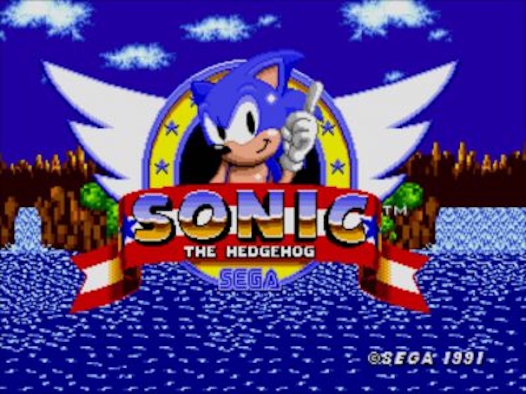
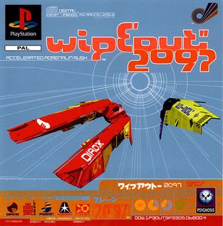
Welcome to the first in a series of posts on developing a 3D Sidescroller Racing Game. By following along with this series you will gain an understanding of what is required when working with Blender, Unreal Engine 4 as well as several other Open Source applications in developing a functional 3D game, that utilizes game mechanics similar to that found in Sonic the Hedgehog and gameplay inspired by Wipeout 2097.
In this post we will start by developing a 3D asset in Blender, that we will then import into Unreal Engine 4 (UE4). We will then use this asset within the Unreal Editor as an item within a side-scrolling game that acts as a pick-up. A pick-up is typically any item within a game world that is collectable by a game character. In terms of Unreal Engine-speak, we would refer to our game character as a Pawn and the pickup as an Actor. Simply put, our Pawn is the character we control within the game and it will interact with our Actor, the pickup object.
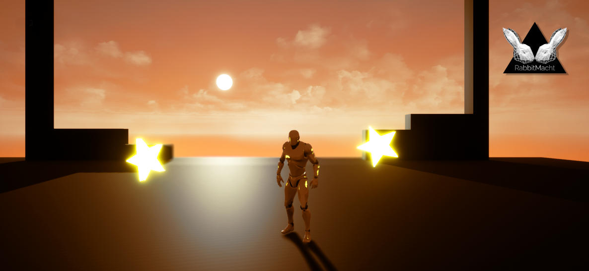
The focus of this post is not on the interaction between the Pawn and the Actor, but rather on the core concepts of developing an actor within UE4. We will develop the pickup 3D model in Blender with special consideration regarding the creation of assets for realtime applications. We will then create a Blueprint Actor with the 3D model in UE4 that has a glowing material and a rotates in-game like many a pickup of simmilar type from other games you may have played.
Prerequisites
No prior programming or game development knowledge is required, as we will unpack both the rationale and implementation behind the fundamentals of 3D games dev. We will also explore deployment to both mobile and desktop platforms in later posts.
You will, however, need a computer capable of running high-end 3D applications, as well as a decent internet connection and a commitment to some level of self-regulated learning.
In order to complete this tutorial, you will need both Blender and Unreal Editor 4 installed. If you would like to find out more about installing Unreal Editor, please read through this post.
You will not require anything more than a basic understanding of Blender’s modelling tools as well as some general background knowledge of 3D. If you are just starting from scratch then you should consider taking this free 3D course before continuing.
Building the Asset
When building game assets there are various factors to take into consideration, it’s always worthwhile keeping an eye of the polycount of your assets, making sure that you are not creating non-manifold geometry as well as creating edge loops that subdivide as evenly as possible as this will assist with creating different Level Of Detail (LOD) objects.
As a pickup is an asset that will be used many times throughout a game level, its polycount becomes exponentially significant to keep as low as possible. Keeping a low polycount is significant as it places less strain on the game’s rendering engine, this ultimately can contribute to making your game play smoother and prevent frame-skipping. Also bear in mind that, it may be a misconception to think that keeping a low polycount is only relevant if you are producing games for mobile devices. Although, the topic of keeping a low polycount is certainly recommended for mobile games its also worth remembering that not only is this a topic of concern for PC gaming but consoles games can benefit from the performance increase as well. When taking into consideration the distribution of a system’s resources for the purposes of rendering and making a game playable, consider that resources consumed for the purposes of transforming and rendering geometry could potentially have been used elsewhere to improve the quality of lighting in a scene or providing smoother physics simulations. In other words, thinking about balancing the load of the rendering engine is not just a consideration exclusively for software engineers but also something that artists and other technicians should always be aware of.
As performance is such an important topic in games development, we will be addressing it wherever possible.
Modelling and Asset Preparation


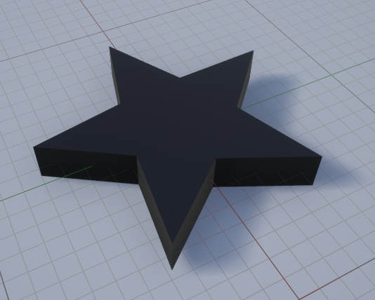
Our pickup is going to be in the shape of a star and although there are many ways in which you could model this in Blender one of the simplest approaches would be to use an application such as Inkscape.

If you use a primarily open-source production pipeline, then Inkscape is certainly a tool you might want to consider adding to your workflow. It is a cross-platform, Vector drawing application and can be used to generate splines that import seamlessly into Blender.
Inkscape has a set of premade shapes that are highly customisable including a star. Once the star was quickly created it was then saved as a vector in SVG (Scalable Vector Graphic) format. This is Inkscape’s native file format. From here the SVG is easily imported into Blender and works as any spline typically would. This is also very useful if you ever needed to tweak the vector graphic as Blender splines, particularly as all the bezier handles generated in Inkscape are retained in Blender.
From Blender simply import the SVG , using Blender’s SVG import plugin.
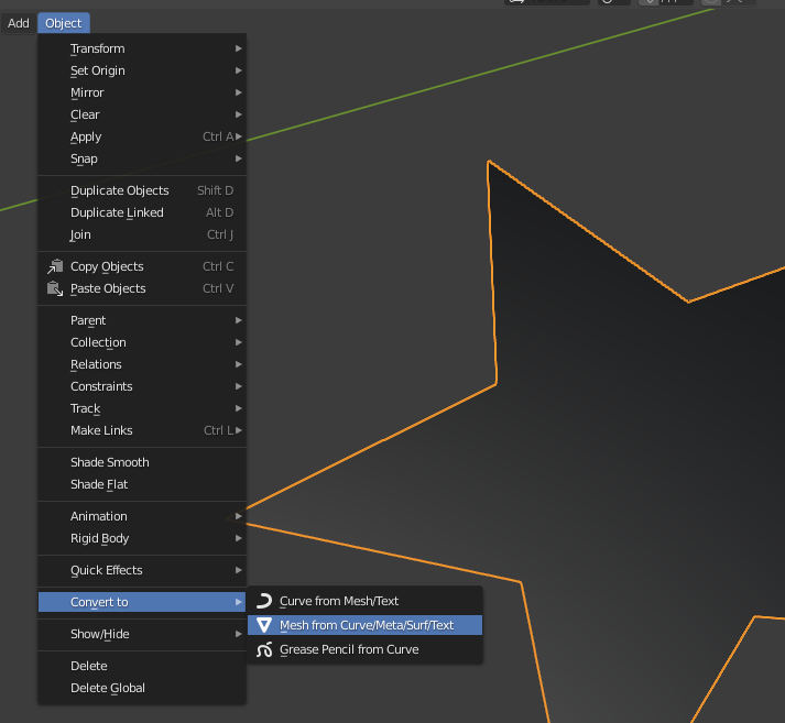
Once the SVG has been imported you can tweak it from here, using Blender’s spline modelling tools. When you are satisfied with the results select the curve and convert it to a mesh.
In order to retain as much control as possible of your 3D assets for your games, converting them to polygons within Blender (and before exporting them) will help you to visualize what the final results will look like. This will also afford you the benefit of being able to address any concerns with the geometry before importing them into UE4.
As a result, it’s recommended that if you have an exporter that does polygon conversion for you there are times when you might want to skip that option in order to retain as much control of the creation for such a critical asset as a pickup that will appear abundantly in some game levels.
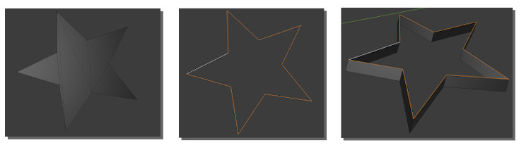
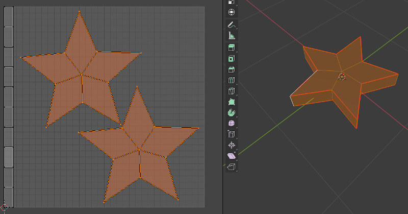
Sometimes in Blender, when converting curves to a polygon object the results might not be what you expect. In our case, as we are dealing with a simple primitive shape although the conversion process resulted in malformed geometry with polygons of inconsistent dimensions, fixing this will be quick and easy.
- In this case the internal edges of the star were selected then deleted, resulting in an outline of the star.
- The edges making up the outline were then selected and extruded. This can be achieved in Blender’s Edit Mode by hitting the e key and moving the mouse/stylus etc in the viewport. To restrain the extrude to a particular axis hit the key corresponding to that axis. In this case, the key combination for extruding the outline of the star was e then z.
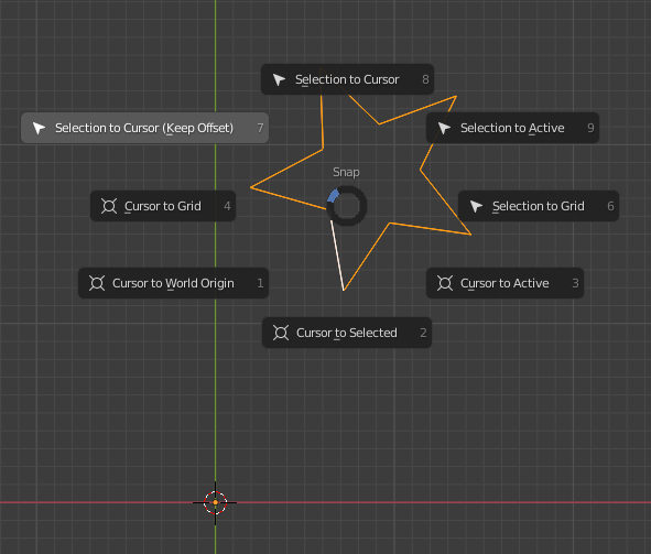
Before exporting assets such as props to UE4 you should always ensure that the object’s Center Of Mass (COM) is in the middle of the object’s volumetric boundaries. The only time when this might not be applicable is when working with characters. In this case, typically your object’s COM could be on the ground plane, in between your character’s feet or the middle of your character’s hip area.
Modelling Considerations for Realtime Applications
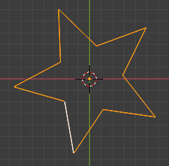
The location of the COM is significant with regards to a games engine as animations applied within the games engine will take the COM into consideration. In our case, we will be making the star rotate around an axis within the game level, this axis is defined by the center of the object’s volume within the game. As such ensuring that the object’s COM within Blender is also centralized to the object’s volume will result in the axes for rotating the object within the game aligning the with object’s COM as you have defined it through the modelling process.
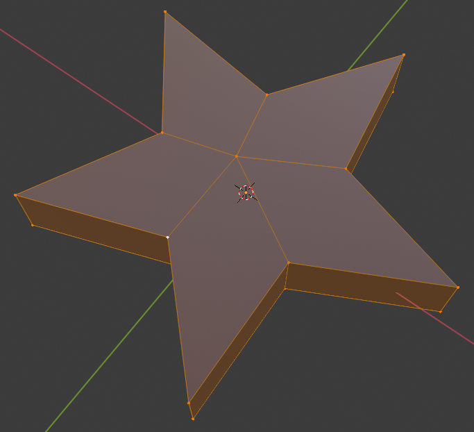
Using Blender’s modelling tools create your pickup asset as you see fit. Some matters to take into consideration when creating your assets include
- Try to keep your geometry minimalistic
- Use triangles and quadrangles but avoid ngons
- Recalculate your geometry’s Normals so that they always point away from the mesh’s interior. This can be achieved in Blender by selecting all vertices/faces and hitting shift-n.
At this stage, you might consider laying out your model’s UV’s. Although it is not always necessary, particularly when dealing with a light source 3D model if you wish to add any textures to your model within the game level then laying out of UV’s will be required.
- When laying out UV’s try to ensure that they take up as much of the object’s texture space as possible (sometimes referred to as 0 to 1 texture space). This ensures that you have the greatest surface area in which to make the texture’s details visible and clear.
- UV’s should be non-overlapping, for the sake of simplicity. Although UE4 does support multiple UV sets/channels which will allow a vertex in one location to inhabit more than one set of coordinates within multiple UV sets. This can simply result in additional overheads with regrads to system resources that can be utilized elsewhere.
- UV islands should match your objects shape as close as possible, for example, the UV map of the star above looks like that of a star.
Once you are satisfied with your model it’s then time to export it to FBX.
FBX is a file interchange format that retains many useful attributes of your 3D assets such as some materials, animation, UV’s and many other properties.
It is a format that is supported by both Unreal Engine and Blender, however, do take into consideration that when you export your 3D assets from Blender to FBX you will be losing some editable qualities. As a result, it is always recommended that you keep your .blend files even after exporting your assets to FBX, in the event that any changes need to be applied to the original model.
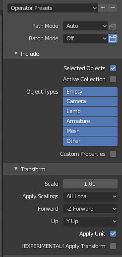
Select the object you want to export, then from Blender’s File menu choose Export FBX. Make sure you have Selected Objects checked for the FBX Export options the other default settings in most cases will suffice.
Setup your Game Project in the Unreal Editor
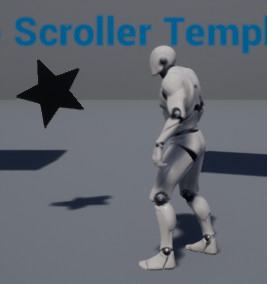
We are going to be creating a 3D side scroller game, in which the character can race through levels collect pickups and try to avoid obstacles, very similar to the mechanics of Sonic the Hedgehog.
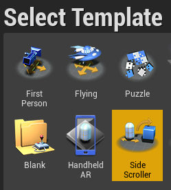
We will start by using Unreal’s Side Scroller Template. These templates are a great starting point for many different game types including First Person Perspective, 3rd Person Perspective and many others. A lot of the basics have already been built into the templates so starting with a template can ultimately save you a lot of time.
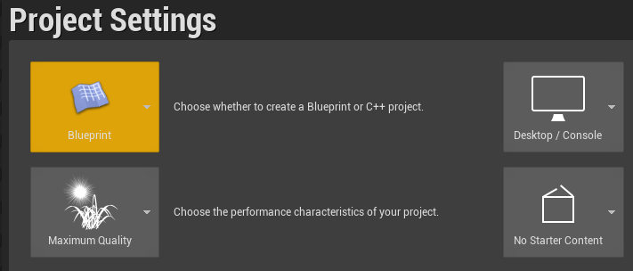
We will primarily make use of Unreal Editor’s Blueprint visual scripting interface. This is, as opposed to, primarily driving the game’s interactivity with our own C++ scripts. Even if you are very familiar with the C++ programing language, there are still many benefits to working with Blueprints as it remains an extremely versatile choice, capable of achieving results quickly and in some cases, the performance increase you gain from working exclusively with C++ might not even be noticeable.
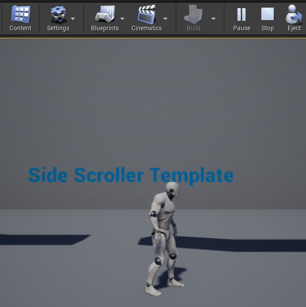
Once you have your new project created you can test the default gameplay, simply by clicking the Play button in the main interface. You can then use your keyboard to control the character in the game.
Once you are done press ESC to return to the Editor.
You might notice that our game is missing some crucial components. We will start by adding the pickup we previously created in Blender to our game.
Import A 3D Mesh Asset
Below the 3D Viewport, you will find the Content Browser. This panel provides a visual representation of the components that make up the game. Assets not only include 3D meshes but also Blueprints, sounds, materials, animations and many other types.
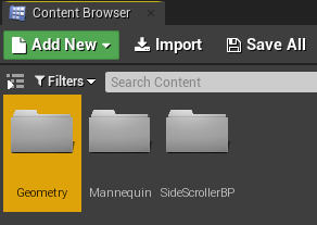
As your projects grow in scale, the need to keep your assets logically ordered and therefore easier to find will become more relevant. As a result, we are going to keep things organized by importing the Star Pickup 3D Asset under the Geometry folder within the Content Browser. Open the Geometry folder and navigate to Meshes.
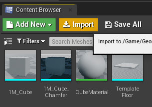
Click the Import button to bring up your system’s file chooser dialogue box. Then navigate to the directory where you saved the Star Pickup FBX file and import it into the scene.
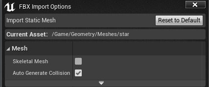
Unreal will recognise the file type you are trying to import (it supports many different file types for importing). It will subsequently load the FBX Import Options dialogue box. Typically the default options will be suitable. Unreal is also generally capable of detecting if the FBX has animation or not and will subsequently check or uncheck the Skeletal Mesh option. As our asset does not have animation there is no need to have this option checked. You can find out more about importing meshes with skeletal animation here.
Once your mesh has been imported you can double click it within the Content Browser to open it for editing. This is applicable for most assets within the Content Browser and not just exclusively for meshes.
It’s worth noting that the mesh has not been imported into the game world. It is simply stored within the Editor for eventual use within the game. In order for us to use the asset in the game, we could drag the asset into the 3D viewport from the main editor interface. The result of this action would be simply placing a mesh in the game, it would have no exclusive, interactive properties. However, because we want our 3D model to have interactivity that we define, we will attach our asset to a Blueprint, then drag the Blueprint into the game world.
The benefit of the latter method is that every time we drag the Blueprint into the game world all of the functionality associated with the asset comes with it.
Create Your First Blueprint
As mentioned there are many benefits to working with Blueprints. We will make our first Blueprint which will essentially serve the purpose of being a pickup in our game.
Although it is not necessary to have any prior programming knowledge in order to use Blueprints, understanding some basic concepts will certainly help when it comes to creating your own Blueprint objects.
Blueprints are essentially a collection of properties and various functionalities. You can define a Blueprints functionalities as well as it’s properties and also access preexisting one too. If you have prior programming knowledge you could think of a Blueprint as a visual representation of a class within the context of the Object-oriented programming paradigm.
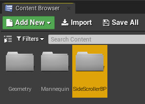
- Within the Content Browser, open the SideScrollerBP folder.

- Right-click on an empty area within the Content Browser panel and select Blueprint Class from the Create Basic Asset menu.
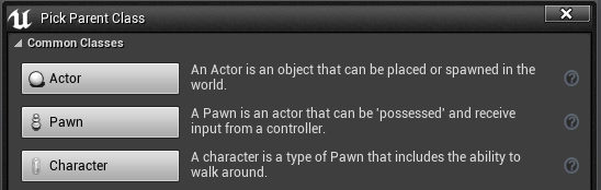
- From the resulting Pick Parent Class dialogue box select Actor. In Unreal an Actor is any object that can be transformed within the game world. This, of course, covers a very broad spectrum of objects including creatures, hero’s, lights, collision objects the sky and the list goes on.
An Actor can be thought of as the most generic class of objects that are placable within the game world.
A Pawn is a type of Actor that is controllable by the player. In other words, a Pawn could be a vehicle, a robot, a person etc. It is the manifestation by which the player interacts with the game world.
A Character is a type of Pawn with more specialized functionality that enables it to walk, run, jump, swim and perform many other interactions with the game world that you could expect of a human-like or personified character.
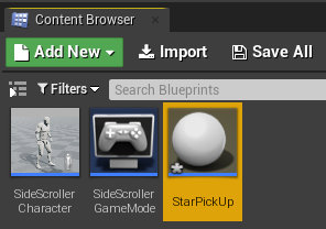
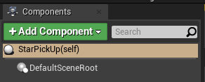
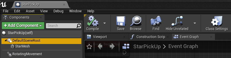
You will now have a new Blueprint in your Content Browser. Name this Blueprint StarPickUp then double-click it to open the Blueprint editor with the StarPickUp loaded.
Working with Blueprint Components
There are three main sections within the Blueprint Editor that we are concerned with.
1. The panel on the left-hand side of the Editor is used to add components to the Blueprint. These components can be various types of assets that you have imported into the Editor (such as the Star Pickup mesh) or assets that are already a part of UE4. You can also add unique properties to Blueprints here.
2. The middle section of the Blueprint Editor is primarily for the purposes of visualizing the Blueprint, how all the components relate to each other as well as providing the ability to modify these connections through a Node-based interface.
3. The section on the right consists of the main panel for editing the details of a component or other selection.
Click on the Add Component drop-down and search for Static Mesh.
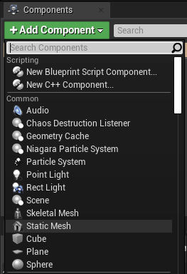
Add the Static Mesh component to your Blueprint. We will now be able to edit the Static Mesh component by including the Star Pickup mesh to our Blueprint.
If at this point you are struggling to visualize what we are attempting to achieve you can think about our project in terms of a hierarchy.
At the top of the heirachy is the game level we are currently working on. This game level consists of all our Blueprints, Characters, mesh objects sounds etc.
What we are doing is currently adding a Blueprint to this level. This Blueprint is made up of a Static Mesh. The Static Mesh is made up of Geometry (polygons) and Materials. The Blueprint itself is also going to include some functionality and properties that will make it possible for our Character and even other Actors in the game world to interact with it.
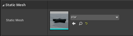
In the Details panel on the right under the section called Static Mesh, you will find a drop-down list. Select the Star mesh that you previously imported and it will now appear in the viewport panel in the middle section of the Blueprint editor.
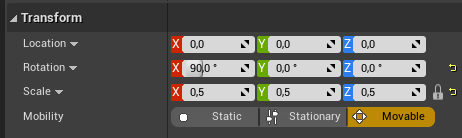
In the same Details section, you will also find the interface for modifying the Static Meshes Transforms. It’s worth noting that you are not editing the Blueprint’s Transforms here. As previously mentioned the Blueprint type we are working on is an Actor and Actors are placeable within the game world, therefore this type of Blueprint will also have transforms associated with it. Again it is best to visualize this in terms of a hierarchy, transforms applied to the Blueprint will have an indirect effect on how the Static Mesh is displayed in the game world. The Static Mesh also has its own transforms, which is what we are editing here. These transforms do not affect the Blueprints transforms as the Static Mesh can be considered as a child of the Blueprint.
A Blueprint is essentially not a tangible object within the game world, however, its components can make it seem tangible.
Now that we have our Star mesh imported and connected to our Blueprint we are going to work on making it look somewhat more interesting by adding some simple animation as well as making it glow. At a later stage, we will add the functionality that turns it into an actual pickup which augments our characters score during gameplay.
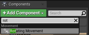
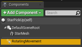
Within the same Blueprint Editor for the StarPickUp add a new component called Rotating Movement. In order to add components to a Blueprint follow the same steps, we took for adding the Static Mesh. This component will be used to add a simple rotation animation to the pickup. You can specify the axis around which you would like the rotation to occur in the Details panel.
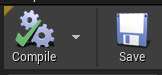
Once you are satisfied with your edits you must compile the results to ensure that there are no errors. As a reminder Blueprints provide a visual representation of the code that would be required to make your game interactive. Compiling, in terms of programming, is the conversion process required between one type of programming language into another. As such, you can think of Compiling in terms of Blueprints as converting the work you have done from a format that is human-readable into a format that is more machine-readable and can therefore run more effectively on a variety of different systems.
As a general rule, you should always consider Compiling and Saving your work before exiting the Blueprint Editor.
Once you have compiled and saved your Blueprint, close the Blueprint Editor. Back in the main Editor click and drag the StarPickUp Blueprint you just saved from the Content Browser into the viewport. If you recall the type of Blueprint we created was an Actor and as previously mentioned Actors are Blueprints that are placable within the game world. As a result, when you drag the asset into the viewport you will notice that arrows appear in order to translate (or move) the asset around in 3D space.
Once you have placed your asset into the viewport, you can test your placement and how your character interacts with your asset by clicking the Play button.
Exit Game mode to return to the main editing interface and double click on the StarPickUp Blueprint in the Content Browser.
You might notice that this time around when the Blueprint Editor opens, instead of seeing the Star Static Mesh you see a grid, where the Viewport previously was (in the middle section of the Editor). This is likely the Event Graph and its main purpose is to provide a visualization of the properties and functionalities of the Blueprint. As we do not have any yet, the interface might seem pretty empty. At a later stage, we will add functionality to the StarPickUp that will allow us to interact with it during gameplay.
If you want to return to the interface showing the static mesh, click on the Viewport tab. From here you can select the Star Static Mesh. You can also simply select the static mesh from the Content Browser and double-click it for editing.
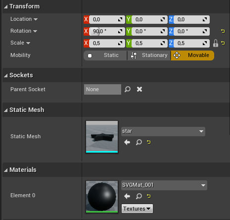
If you are currently in the Blueprint Editor with the Star Static Mesh selected, in the Details panel on the right section of the Editor you will find a menu for the Mesh’s Materials. You can double-click on the swatch (which should look like the thumbnail of a sphere) and this will open the Material Editor.
Node-based Editing for Materials
Unreal Editor provides an intuitive Node-based editing system that is consistent not only for editing materials but also for designing interactions with Blueprints. If you have previously worked with Blender’s node-based editing system when building materials you will find many similarities in terms of building materials within the Unreal Editor too. Nodes can be added by right-clicking on an empty area within the grid area (middle section) of the Material Editor. You can create connections between Nodes by dragging handles from one Node’s socket to another Node’s socket. When you attempt to make a connection that is invalid the Editor will prompt you with a message in red text.
In order for your mesh to render it will require a material, how that material renders will be determined by the connections we make between the various nodes in the Material Editor.
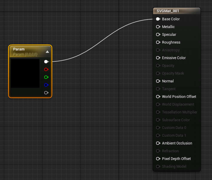
A default Material is created when you import a Static Mesh that does not already have a predetermined material associated with it.
In our case, we have a material with a Scalar Parameter connected to the material’s Base Color. You can use this Parameter Node as an easy way to change the main color of your 3D object. This channel is also similarly referred to as the Diffuse Color in other applications.
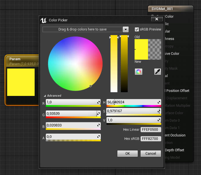
Simply click on the swatch and a color picker will appear. Change the color, keeping an eye on the Old and New values, then click OK. The Parameter Node is made up of multiple sockets consisting of composite, red, green, blue and alpha channels. Any channel that can accept a number as an input can accept red, green, blue and alpha as an input. Only channels that can accept multiple values will be able to accept the composite channel as an input.
If working with Node’s in this way seems somewhat confusing, not to worry as we will be revisiting the topic throughout the series in various different interfaces. It will take a bit of practice to understand what qualifies as a valid input, but it certainly does not need to be a complex topic for concern at this stage.
We are going to start off by keeping things as simple as possible, as a result, we will use the existing parameter node in a series of connections that contribute towards making our star pickup glow.
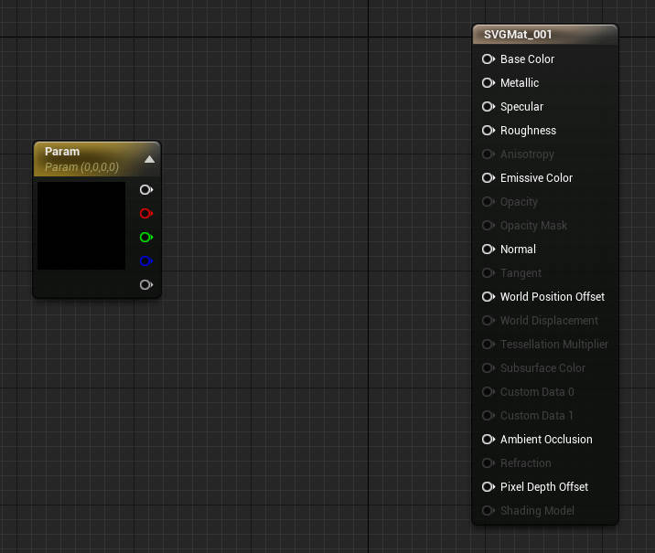
You can disconnect two nodes by holding Alt and clicking on the connection you want to delete. To be clear we don’t want to delete the Node we simply want to delete the connection between the Base Color and Parameter composite channels, therefore just delete the connector.
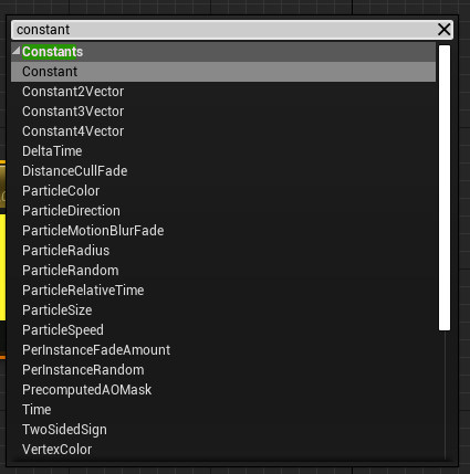
We are now going to add a Node called a Constant. A constant is a special type of value (or data) that does not change during gameplay. With this in mind we will use our constant to set a value that we use to control how much we want our Star PickUp to glow.
Right-click on an empty area within the Material editor grid viewport to add a new Node. In the search field that appears type constant and select Constant under the Constants section that is filtered by your search.
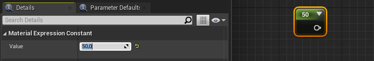
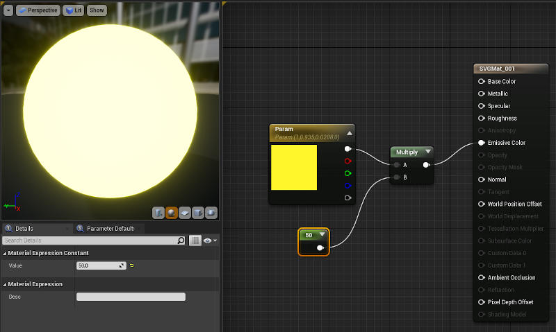
A Constant Node will appear. You can edit its value by selecting the Node and giving it a value in the Details panel. Setting this value to a number anything above 10 will make the glow on your object more distinguishable. The higher the value the greater the glow, in some cases a value of 50 might be used to achieve a good balance.
As you will notice your material will still not be glowing as of yet, this is primarily because we have not finished setting up the rest of the Nodes and nor have we completed making the appropriate connections.
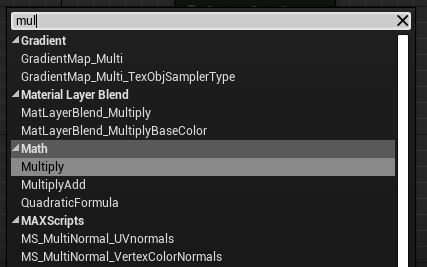
Next, we will add a Multiply Node. Again, right-click on an empty area and search for multiply. The Multiply Node consists of two inputs and one output.
Input channels of Nodes will always be on the left of the Node and output channels on the right-hand side. Logically, when making connections between Nodes drag an output handle to the appropriate Node’s input channel. This is not something you would typically ever do on the same Node.
We are now going to finish our material by making the appropriate connections. As noted the Multiply Node has two input channels, the purpose of the node is to take an input from channel A, multiply it with the Value as input from channel B then return the result through the output.
In our case, this is significant because all color channels have a minimum and maximum setting depending on the software you are using this could be represented as a range between 0 to 1 or 0 to 255. When pushing these representations of color values beyond their predetermined ranges, the result is that the material can start to appear as being self-illuminated. By taking the results of these exaggerated values and returning them to the Emissive Color channel of a material, a bloom effect is then achieved. This bloom effect is what creates the impression of the object glowing.
It is, however, worth noting that the object is not necessarily glowing, as if it were glowing it would also be casting light on the environment in which it is placed. Therefore, the effect is simply a simulation that does not match real-world physics unless you are using a more current build of UE4. In builds 4.6 and greater the emissive material is, in fact, able to cast light on the environment.
Although it is possible to simulate the effect of the material lighting the environment in versions of Unreal less then build 4.6 you would have to consider how this will affect performance during gameplay.
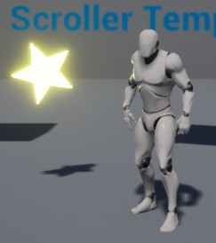
As previously mentioned performance is of great significance when developing games. Take into consideration that this Star PickUp will appear many times within a level. To visualize this more clearly think about how many times coins appear within a Sonic the Hedgehog level. As a result, wherever it is possible to improve on the performance of an asset during gameplay, it is worth taking into consideration the balance between the quality of rendering versus performance. However, in some cases, you might be able to plan the implementation of an asset without having to make compromises yet still gain from the potential of a performance increase.
In our case, this is crucial when taking into consideration how many times the Star PickUp will appear within a single level as each instance added to the viewport has the potential to negatively impact on the game’s performance, in other words how smooth the game plays or whether it skips frames on some devices.
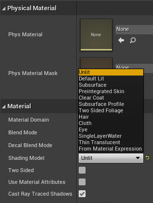
Unreal provides various Shading Models when working with materials. These Shading models have been optimized in some way to reproduce specific qualities of real-world materials such as cloth, hair and many other types. However, one of the Shading models does not represent a real-world material, as it is intended to ignore the physical properties of light. By setting the Star PickUp’s Shading Model to Unlit we are just using the materials Emmissive Channel to control the visible qualities of light related to the object. This could potentially result in a significant performance increase as physically-based light properties do not need to be calculated for every instance of the Star PickUp.
On the other hand if the object you wanted to add a glow to also required physically-based lighting properties, then the Unlit Shading Model would not work. For example, if your model also made use of a Normal map or had specular highlights.
Once you are happy with your pickup’s material click the Apply then Save buttons and close the Material Editor.
When you are back in the main editor, drag a copy of the Blueprint asset you just created into the viewport if it does not already exist, or drag out as many copies as you want. Then go ahead and test your game.
In this post, we were introduced to many of the basic editing interfaces that the Unreal Editor uses consistently for different components making up a game. We also touched on some topics that should be taken into consideration when exporting assets from Blender for UE4.
In the next installment of this series, we’re going to take a look at how to add interactivity to the assets we imported as well as how to create animated assets in Blender that will be imported into our game.