I started a new project a few days ago.

After having a look at my gallery, I decided that none of the images demonstrate my current skill level.
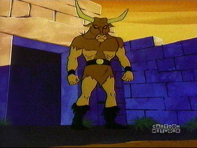
So in an attempt to improve the current state of my gallery I started modelling a Minotaur which will form the main character for a new set of renderings I hope to produce with it. And why did I choose a Minotaur? Well like all good things the idea occurred to me while watching an episode of Scooby Doo!
…and Nick Papas (a visiting art student to the Greek village where the episode was set) who turned out to be the Minotaur, was in fact smuggling rare Art works plundered from the war in barrels filled with olives; which were subsequently set to be shipped to England and sold on the black market. Aha a clue!
My Minotaur is however going to be a little different than that of the Classic 1979 Scooby Doo episode. Since making high quality 3D renderings is a lengthy process, I decided to start posting the progress of the image making process here and also discussing techniques that I use when making 3D characters from start to finish.
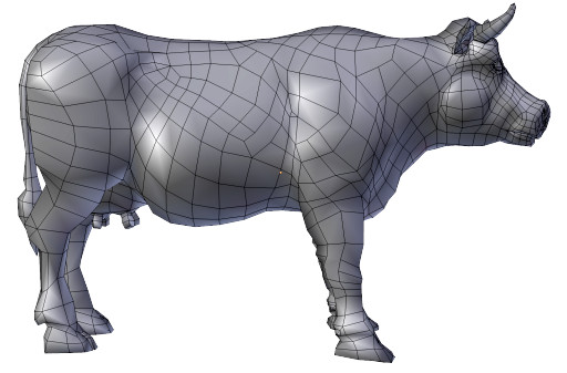
I’d previously made a 3D model of a cow in Blender which I released for free under a CC0 license and can be downloaded at Blendswap.
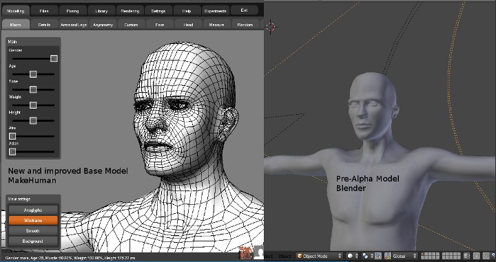
I’d also contributed my modelling services to an open source project called MakeHuman which is used to generate various human type 3D models and was still in Pre-Alpha stage at the time
The application has since received many updates that have taken it to an Alpha release and vastly improved models, interface and customizations.
So instead of starting my minotaur base model from scratch I decided to combine my realtime cow model with the makehuman base model. The major issue with using this technique would be creating geometry that has contiguous edge loops, and minimal polygonal triangulation. The makehuman base model is a great example of this type of geometry as it is made up entirely of quadrangles (4 sided polygons). This allows for the most natural (and predictable) topology deformation in humanoid characters. However, it is not always necessary for every humanoid mesh to be made up entirely of quadrangles, depending on what the model will be used for using a combination of quadrangles and strategically placed triangular polygons can contribute to improving your systems performance when rendering a realtime 3D model in your applications OpenGL viewport and at the same time not compromising on the quality of the “look” of your model. The “look” of the model is what the model appears like in the final product and if you have done a good job of modelling it the concepts used in the model’s underlying geometry should be
completely abstracted to the viewer.
Early Days
So to sum it up…
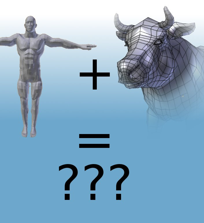
And that is basically what I started with. I then deleted the components of the two models that I did not need trying to preserve as much as I could of the original models, this would effectively reduce the amount of additional modelling I need to do.
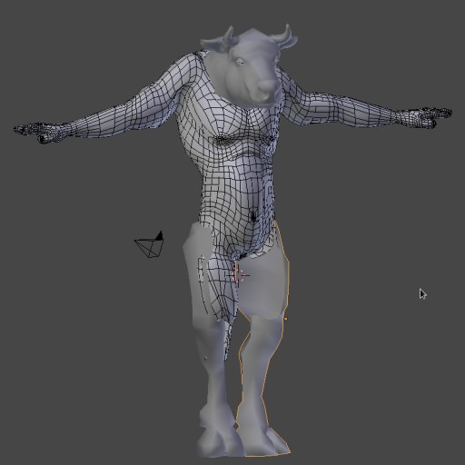
As you can see from the makeHuman base model I kept the torso, arms and thighs. From the cow model I kept the head and the lower legs.
As certain areas of the mesh needed to be moved and rotated to accommodate for a completely different skeletal structure to that of a human, I decided to create a quick FK (forward kinematics) rig, bind the rig to the combined model and rotate the FK rig into the new default/rest pose for this model then delete the rig applying it’s transforms to the model.
Using this technique for modelling can be far more effective than selecting vertices and transforming them, as the modifier binding the geometry to the rig will help to prevent hard deformations that invariably result in large groups of vertices getting tangled and lost within the negative space composing the model interior. These would then have to be manually moved into new positions. A very time consuming process.
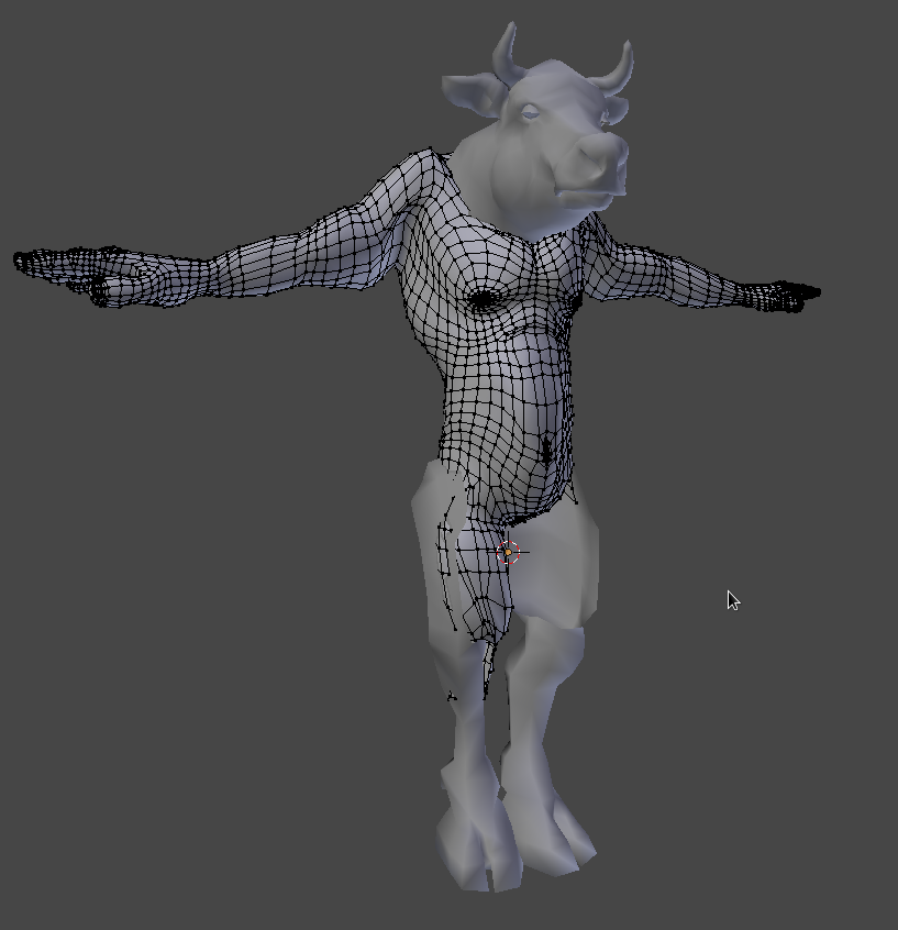
Entire sections of the model can now be transformed into new positions without having to worry too much about intersecting geometry.
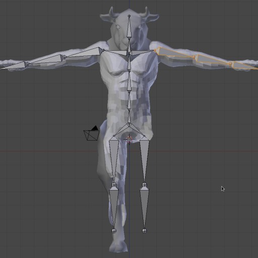
Once the main components making up the base mesh have been scaled and moved into place, then joined into a single mesh, the model can be bound to the skeleton and rotated into position using FK. Setting up a proper rig with IK and other controllers would be overkill, it’s also worth noting that the Non Manifold edges of the components that will contribute to the completed base mesh do not need to line up at this
stage (as is demonstrated in the image above). A rough approximation of where the majority of vertices will reside in relation to other vertices from the other mesh components is all that is necessary at this stage. What this means is that accuracy is not the issue nor is determining the direction of continuous flowing geometry, what is important is that the model resembles an approximation of the final output, in
terms of form. Once the various mesh components have been joined together and bound to the temporary rig you can concentrate on the models default or “rest” pose.
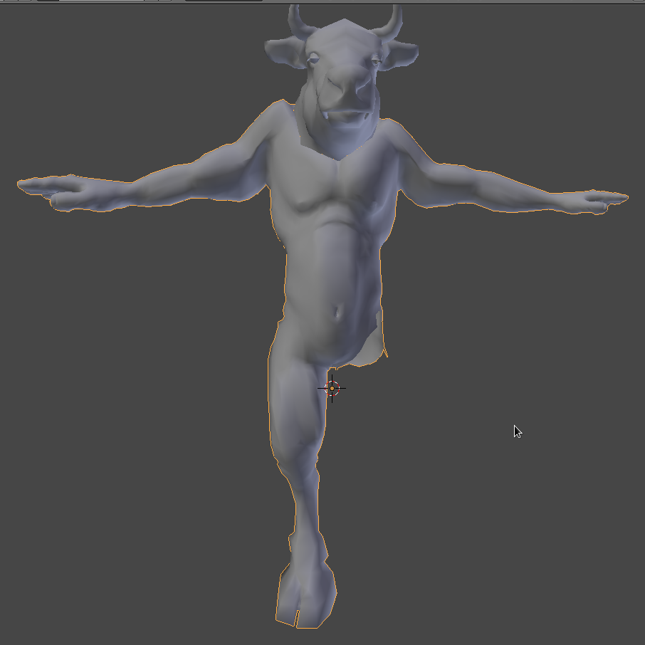
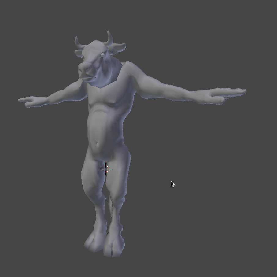
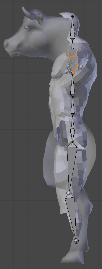
In the above image the model has been moved into it’s new rest pose and the skeletal transforms have been baked into the geometry. I chose not to delete the skeleton in the event that I need to move entire limbs or other regions of the model at a later stage in the modelling process once it becomes more evident where the character is most likely suffering from the effects of gravity and mass exerted on his underlying
skeletal structure. This is more to do with the “look” of the model rather than full-filling a specific technical criterion.
Mirror, Mirror on the YZ plane, help me model with speed to gain
As you can see I have not mirrored the model yet (as is visible in the above image) and as a result I’ve only attached one limb to the main torso section. Doing this any more than once is a complete waste of time (in this particular case). So after attaching the limb, and again I’m not interested in continuous edge loops at this stage, I delete half of the model and apply a mirror modifier to the remaining half. Which
will cut the amount of time I need to spend on certain modelling tasks by half.