Posted on Leave a comment

Minotaur XII : Optimizing a Poly Count for Rendering

Optimization Testing

Early multi-angle, animation test with the Minotaur character.

Synopsis

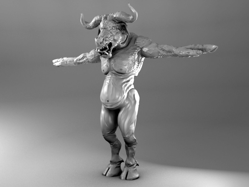
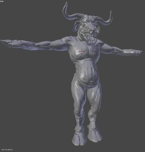
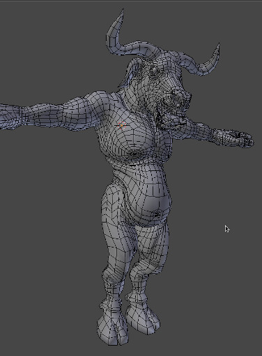
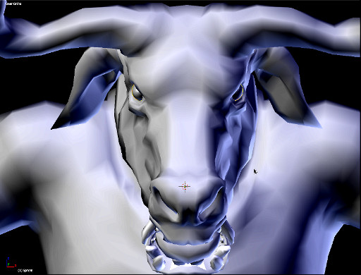
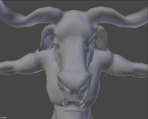
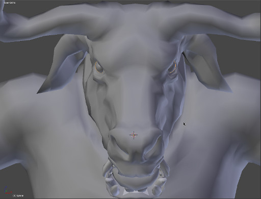
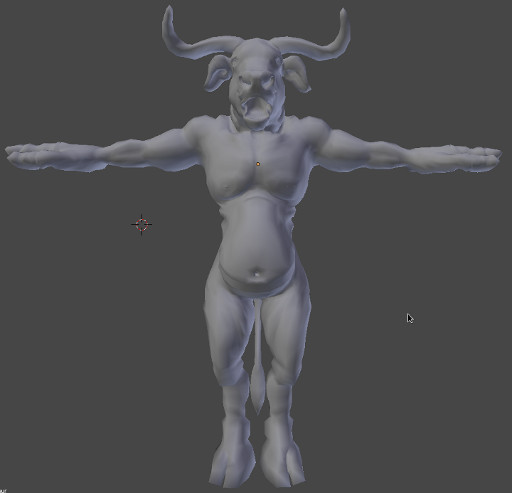
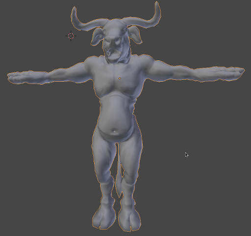
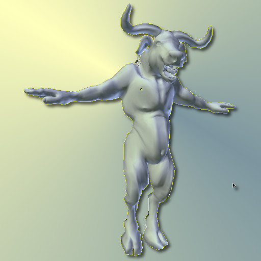
The model and armor take about 4.5min/fr to render. Using the rendering technique outlined in my previous post on skinning (“Minotaur XI”) the Minotaur in this animation is subdivided 3 times at render- time, then targeted to a high resolution sculpt which was baked at level 03 to displace the subdivided geometry (see “Minotaur XI: Proxy Model Setup” for details). The high-res sculpt is saved externally and linked to the current render file, this reduces the file size for this particular character from approximately 0.5GB to 100MB. Smaller file sizes help clear up unnecessary RAM usage, which has been reduced from 8GB (RAM) + 3.5GB (Swap Space) to current usage of 4.1GB at render time and 2.1GB when loaded (Blender startup uses about 1.3GB of RAM for this setup). This reduction in RAM usage accounts for the reduced render time which was previously 30min/frame to the current time of 4.5min/frame. This makes a vast difference in pre-rendered animation when you consider that approximately 25 frames are required to account for only a second of animation.

Testing Criteria

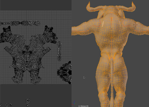
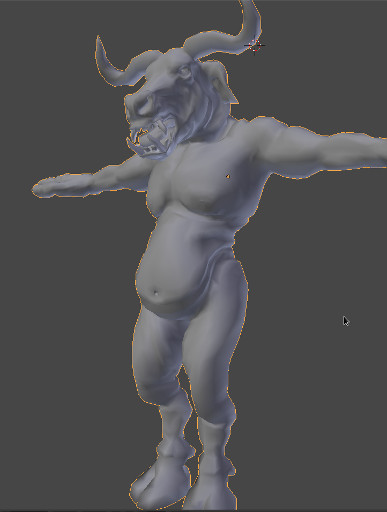
Only Two separate passes of 1) character and 2) armor was used in this render. No texture maps have been completed yet, as this render is mainly used to gather data on three main categories:

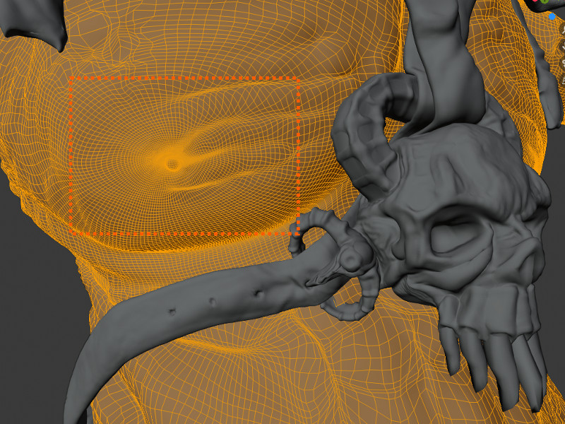
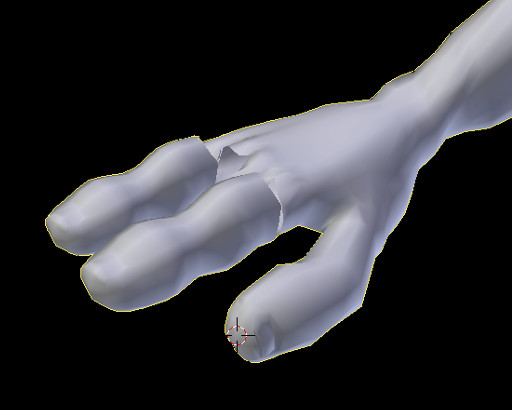
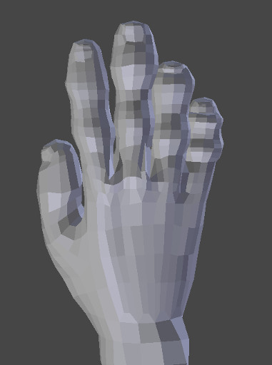
  • How geometry is being displaced at render-time over the entire mesh
  • How normal mapping affects the displaced geometry
  • And render timings on optimized models.

Armour Geometry Targeting Displacement and Normal Mapping

Several basic renders were also created testing the same criteria in the armor, the results follow.

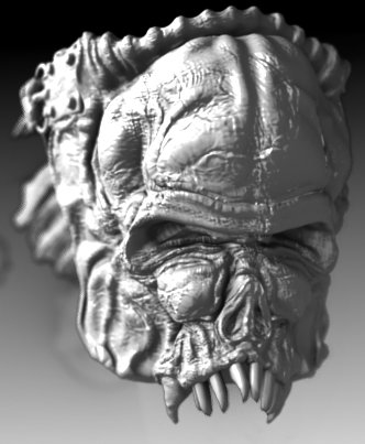
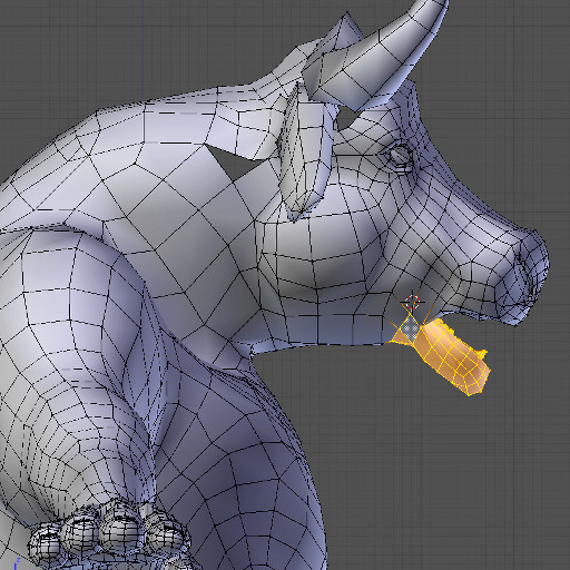
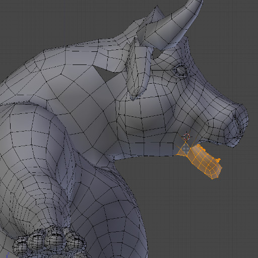
The preceding image is of the Minotaur’s right shoulder guard. The lighting is particularly “unflattering” in these images as certain areas of the geometry are highlighted for consideration. Any areas that indicate stretching of the normal map will need to be addressed with multiple UV layouts, but this will likely only be addressed at a much later stage when the camera has been locked down for the final shots.

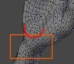
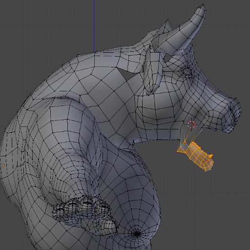
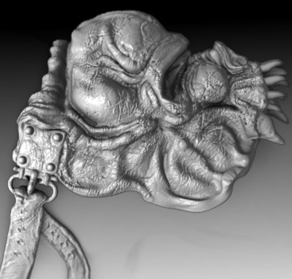
The following image is a shot of the right shoulder guard from the back of the character. It’s evident from this test that geometry displacement did not recess the polygons comprising the holes in the strap adequately, as was the case in the sculpt data. Custom transparency maps will need to be used to compensate for this lack of displacement on the character’s armor straps.

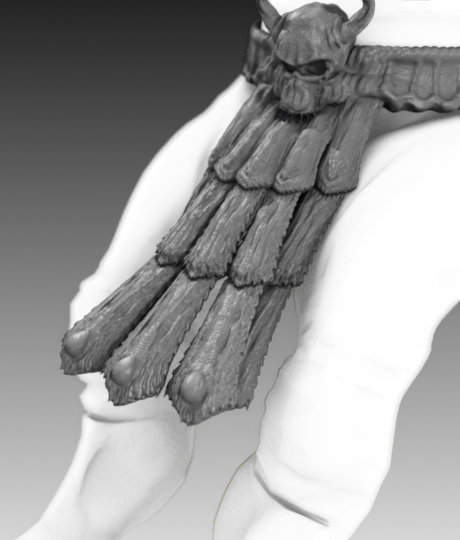
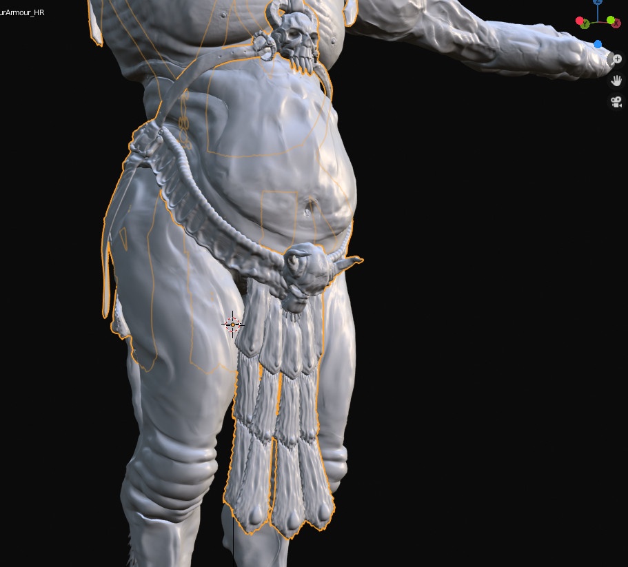
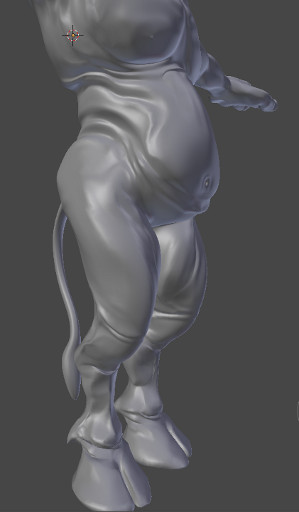
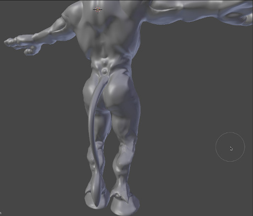
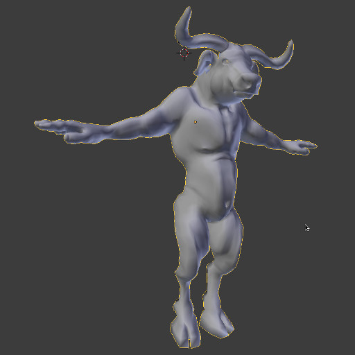
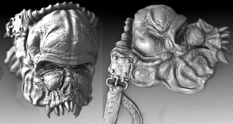
The preceding image is of the lower body area with the toga armour between the legs. The sculpt data on this geometry was exceptionally high and as a result, is a serious consideration with regards to detail loss during optimization. However, the geometry displaced considerably well when the Simple algorithm for calculating subdivisions was chosen (as opposed to the standard Catmull-Clark method). Subsequently, the toga armor straps only required a single level of subdivision (the lowest for all the characters components). The Toga is also planned to be a hairy surface in the final render, so a large amount of detail would have been wasted with more subdivisions.

Posted on Leave a comment

Minotaur XI : Proxy Model Setup

Skinning is the process of attaching geometry to an underlying skeleton or armature. We then use the armature to pose the model and simplify the process of animating it. There were several issues that had to be considered when skinning the Minotaur character, of which the main issue was inconsistent Normals.
This post will cover a method I discovered on how to correct this issue without having to resort to a lattice/cage deformer and still allowing for the (very important) proxy object method of rigging.

What’s so bad about inconsistent Normals?

As all polygons will have two surfaces, the software you are using will need to know which of those two surfaces is pointing away from the mesh. Geometry’s Normals should be perpendicular to the surface of the polygon pointing away from the outer surface of the mesh. This is not only important for skinning but also for sculpting.

📝 If you are feeling a bit lost a this point, you can brush up your knowledge on Normals in my free 3D course

1. Easy Fix

The best way to ensure consistent Normals in a 3D package is to Apply or Bake all transforms of the model, then select the model’s faces, normals or vertices (depending on your 3D software) and recalculate the direction of the selected component’s Normals.
In Blender this is really easy as ctrl-n will automate this process for your selection. In other software you might need to turn on “show surface normals” to ensure that the objects Normals are pointing in the correct direction, and if not select the erroneous component and choose “flip normal”. This will reverse the direction of the selected component’s normal.
You might come across inconsistent Normals when sculpting with a tool that translates geometry away from the surface or into the surface of the mesh. For example, creating a stroke along the surface of your mesh (with a sculpt tool such as “Draw”) could start as concave but end as being convex. In this case the Normals are possibly inconsistent and need to be addressed.
If this problem is not addressed and the same model is used in skinning, that model is likely to suffer from poor deformations.

Problems Arising From The Modifier Stack

Although this problem might be trivial at times and fixing it is simply a matter of performing the steps outlined above (see Easy Fix), sometimes the above method will not be practical as it does not respect an objects modifier stack. If you are using one or more modifiers in your objects stack such as multi-resolution or other modifier that deforms the object at a component level, reversing the Normals of the base mesh will effect everything in the stack above it.


Secondly, if you are using a multi-resolution mesh you will probably know that working with a mesh at it’s highest level of subdivision is simply not practical. The problem is that in order to recalculate the object’s Normals you need to bake the modifiers into the object’s stack before you can recalculate the Normals, and recalculating the Normals of a high resolution mesh baked from a multi-resolution modifier is not practical and sometimes not even possible (for lack of system resources).

2. Normal and Displacement Maps Method

If you have come across this problem, one of the most common solutions seems to be to bake out a normal and displacement map from the sculpt data although, I found that this method produces results that are in some ways vastly different from renderings that include the highest level of sculpt data.
However, as you can see in the image below, the results are not completely unusable, but warranted too much of a compromise on quality to be used as a sole solution.

The above image demonstrates the results of this method. It is a single subdivision from the sculpt data baked into the mesh, this means that the mesh being used for the final render is a realtime mesh. Since the multires has been applied/baked into the mesh the normals can be recalculated safely. The model then has a Normal map and a Displacement map (which were both previously baked from the highest level of sculpt data) applied to it. A subdivision surface modifier is then applied to the model and it’s levels are increased for render time (the viewport model remains realtime).

Cons

As you can see the results are not too bad, but substantial detail is lost in the lower body and the outline of the model is exceptionally smooth in an undesirable way.

Pro’s

The main benefit of this method is that it computes optimally for realtime viewport interactivity and has a relatively short render time. If your character is not a focal point and nothing closer than a wide shot is required you’ll probably be able to achieve useful results from this method.

3. Weight Transfer and Mesh Deform Method

One of the methods I am familiar with in dealing with this problem is to create two models a realtime model and another high resolution model from the sculpt data. The realtime model is then skinned and animated, the high resolution model is then bound to an identical or the same rig before render time and the weights of the realtime model are transferred to the high res model. As a result the only process intensive task performed on the high resolution model is rendering. No manual production tasks need be performed on the high resolution model, which would be impractical. This tool set has existed in Maya since version 6.5 (if I’m not mistaken).
I was expecting to use this method in Blender, however it slowly became undeniably apparent that Blender does not (as of version 2.63) have a transfer weights option that matches the usability that I’d previously been accustomed to.

The issue is being addressed by user 2d23d and you can read about it at this post on blenderartists.org
The addon looks very promising and I sincerely hope it continues to be developed, as at present it is unable to address exceptionally high levels of geometry. Which made it unusable as a solution in this particular situation.
Other methods are suggested in the above thread such as the usage of a “mesh deform” modifier, which I think was added to Blender during the Apricot project which resulted in the open source game Yo Frankie!
Unfortunately, the mesh deform modifier proved to be the most cumbersome and difficult method (particularly as weight transfer only takes a couple of minutes in Maya). Creating the deformation cage took a total of 10 hours, and the results were unfortunately still unusable. I would recommend that anybody attempting to use this method creates a cage from scratch and do not try and convert a base mesh into a cage, especially if your model is not symmetrical or has a lot of sharp edges.

If I had been able to apply the mesh transfer method I would have ended with a result similar to the one below.

The above image is a rendering of the actual sculpted model at it’s highest level of resolution. As you can imagine this is a mammoth sized polygonal model, for example the cracks in the skin are geometry and not a normal map. Looking at this rendering and the final render below it’s difficult to tell them apart, however the most notable difference is in the characters tail which you can see faintly behind the character’s left calf. The highest level sculpt render (above) shows protrusions extending from the end of the tail, the same protrusions created from the realtime model (below) do not extend as far. This can, however, be corrected by using a level 05 sculpt for the shrinkwrap target (method explained below) and increasing the subdivision surface levels at render time. But in this case it would not warrant the
additional time that would be added onto the render as the end of the tail will mainly be covered in fur.

4. ShrinkWrap Method

The method that I finally settled on turned out to be exceptionally simple and takes only a few minutes to setup.

  1. Bake a Normal Map from the highest level of sculpt data (and a Displacement Map if desired).
  2. Create a Realtime model and a High Resolution Model to be used as a reference at render time.
    The High res model does not need to be baked at the highest level of sculpt data. I chose level 3 of 5 because at level 3 all indentations in the mesh are visible therefore breaking up the smooth outline problem mentioned in earlier render tests (see Normal and Displacement Maps Method).
  3. After ensuring that the model’s normals are facing the correct direction, for both models (see Easy Fix). Place the models on different layers and hide the high res model so as to speed up viewport interactivity and apply the Normal and Displacement maps to the realtime model as per usual.
  4. Select the realtime model and apply a Subdivision Surface Modifier (so as to increase the poly count at render time as this will be the final model used for rendering), then add a Shrinkwrap modifier and target it to the high res model. Order is important here, as the surface needs to be subdivided at render time before it can be shrinkwrapped to the high res model.
  5. Bind/Parent the realtime model to an armature, with the armature modifier completing the stack in the setup. Once again, order must be respected this is so that the armature deforms a representation of the high res model (by means of the other two modifiers) at render time.
    As you can see using this method the high res model remains hidden and out of the way as it requires no manual process intensive work such as weight painting, binding (to cages or armatures) and no proxy mesh data transfer is required either. The longest part of this setup is baking the Normal and Displacement maps.

The above image is the final result, as you can see the highest level of sculpt detail is retained, for example the bumpy and folded knee area in this render can be compared with the initial rendering for the Normal and Displacement Maps Method where the knees are extremely smooth. Also note that the models outline is no longer smooth, either.
Another benefit of using this method as opposed to rendering high resolution geometry from a viewport (such as in the weight transfer method), is reduced render times. This model takes approximately 5 minutes to render compared to the image shown in the “Weight Transfer and Cage Deform Method” section that takes approximately 30 minutes to render (as my system has to resort to swap space in an effort to cache 8GB (RAM) + 3.6GB (Swap Space) of polygonal data).
PS. You might have noticed that the Minotaur suddenly has some color but I’ve not mentioned anything about it until now. That’s because I’ve started texturing him, but as you can see this is not yet completed.
So you can expect a post on materials, textures and rigging soon!

Posted on Leave a comment

Minotaur X : Sculpting Armour

This image is of the highest level multi-res sculpt which, at level 5, is about 1,4 million polys for this model. Since this is just a test render mainly to see what the character currently looks like when wearing the armour, the armour is rendered at a low resolution. The Minotaur’s lower-body draping-clothing goes up to level 7, it is rendered here at level 4 in the front to level 1 at the back. The depth of field effect that this creates is merely coincidental and no post production is done on this image (as it is for testing purposes only).
The Minotaur sculpt data is about 95% complete in this picture, and attention needs to be directed towards the hands, mouth area (where removal of symmetry has begun). The final stage of the the Minotaur’s sculpt can only be completed when the armour sits flush against the characters skin, which would subsequently cause indentations in the flesh and possible abrasions. The highest level sculpt is not created with symmetry, but in order to emphasize the effect lower level sculpts often need to be readdressed so as not to create the impression of the highest level data looking like it’s been painted on the model, but is more solidly integrated into the characters anatomy.

Posted on Leave a comment

Minotaur IX : High Resolution Sculpting

These are some level 5 renders. This model won’t go beyond level 5. In these two renders the top half of the Minotaur is almost done and the bottom is only sculpted to level 4.

It’s worth noting at this point, that the technique used for sculpting this model is not typical as sculpting is performed non-destructively. In other words, sculpting does not alter the model’s topology by means of Blender’s Dyntopo technology instead sculpting is performed by simply displacing existing vertices on the model.

This basically means sculpting on top of a Multiresolution Modifier.

Although this technique, has over the years, tended to fall out of favor over the almighty Dyntopo, it still has it’s benefits. I would not say that either technique is better or worse than the other they are just simply different approaches to solving similar problems. As such, one will be beneficial in some areas where another technique will be less so.

Dyntopo

One of the most alluring characteristics of Dyntopo is the natural approach it lends it’s self towards. When using Dyntopo you don’t need to be concerned with technical matters such as topology, the propagation of high level sculpt data to the base mesh and the implications of the inverse. You don’t need to concern yourself with the even distribution of subdivided polygons over your model and how topology can be used to influence the weighting of distribution, thereby salvaging valuable system resources and forcing detail only in areas where necessary. …Not at all, as Dyntopo will easily handle the matter of adding detail for you by subdividing polygons according to the abstraction of a “paintstroke”. Which is of course exactly what you should expect, as an artist, after all.

Nonetheless, with all of these pro’s there must be some cons. Well, I wouldn’t go so far as to call them con’s as much as caveats of which the most obvious is the lack of consideration for continuous edge loops, quads and all matters relating to generating decent topology for the purposes of an animatable character, in general.

Ultimately, what this translates to is that if you wish to utilize your character for animation purposes it would not be recommended that your model (you have just spent all this time sculpting) is itself, physically included in that pipeline. Typically, what you would do in this case is retopologize the model and bake a normal map from the sculpt data. Sounds easy enough? Well, that depends on your skill level and also if you have any fancy tools at your disposal.

Either way you look at it, topology does certainly play an important part in ensuring that characters intended for animation deform in a predictable manner. Whether you attain good topology through retopologizing (as previously discussed) or whether you take the non-destructive approach as outlined in the Minotaur character, is a matter of what suits your needs at the end of the day.

Level 5 Sculpt data on a Multiresolution character

Non-destructive Sculpting

For the purposes of this character, I opted for the non-destructive approach just because I wanted the benefit of not having to complete the sculpting process before I was able to effectively apply the first useful texture map to the character. I also like working on more than one area of interest at a time, this way I can experiment with sculpting and texture mapping simultaneously and immediately see the effects of how each aspect of character development influences another. These effects can easily be visualized through a software render that would give me an arguably, more accurate representation of the final output. That, to me, can also be quite a natural approach to character development, as a whole.

In the above image you can clearly see that this model has not been sculpted with Dyntopo, as even at the higher levels of sculpting the edge loops continue to follow the base model’s topology to a large degree. The high res sculpted data effectively forms part of the production pipeline, with this technique.

LOD

Another benefit of this technique is that if you plan on exporting your character for a games engine, you will already have various Levels Of Detail (LOD) models, each with the same UV layout and vertex ordering. An LOD variant can then simply be created by collapsing the model at a predetermined multiresolution level. For example, in this model I would effectively be able to create 5 LOD’s with a few simple clicks and retain complete control over each model’s topology, without having to rely on a plugin that automates retopologizing, to save time. That can be quite a big plus in terms of game engines, particularly for next gen engines that can crunch through millions of polys per second and utilize what would typically have been film quality assets.

As the vertex ordering is exactly the same on all of the LOD’s you will also be able to use the same rig, weight maps and subsequently animations on all of them, but we’ll get into all of that a little later.

For now, I’m happy with the main sculpt and so I can move onto the next step. Of course, it’s worth also noting that as the sculpting process is non-destructive I don’t have to decide that I’m done with sculpting at this point in time. In fact, I could revisit sculpting at any stage in the future including after the character has had UV’s laid out, been texture mapped, rigged and animated.

As a result, you can see there are still alot of benefits to using this sculpting technique. Although, I am perhaps over-simplifying some of the complexities of this setup you will nonetheless come to see that it is certainly achievable and definitely effective in production as we discuss the setup in more detail in posts to follow.

Posted on Leave a comment

Minotaur VIII : Sculpting and System Stability

Sculpting

I generally lay out UV’s before sculpting commences…


This may not be an ideal solution in some cases as vertex translation of the base mesh could occur, when the higher level sculpt data is propagated to the base level.

In other words there is always the risk that high level sculpting could inadvertently modify the basic form of the character. If you have a texture map applied using the current UV layout, stretching will occur, as a result of vertices being translated to match the new form changes from snapping vertices on the base mesh to the higher level sculpt.
However, I won’t apply a texture map to the model until the sculpt can be applied to the base level mesh, in order to avoid this side-effect. So why not just do the UV layout after sculpting is done, and you’re ready for texturing?
Well you could, but I prefer having an idea of what my UV layout will look like before completing the sculpt, I can then bake out normal map tests while sculpting. This gives me a clear indication of whether my UV’s are spaced out enough to provide adequate room for sculpt details at a reasonable texture size.


My UV’s can then accordingly be tweaked again before arriving at a final layout.

System stability is also a big issue for me.

Sometimes the systems I use to create models have a limited amount of RAM which could be as low as 8GB. Although this might be adequate in many circumstances, it will require that I adopt a different approach for the level of skin detail that is needed with this model. Basically, it will mean having to cut the model up into smaller components or “dice” the model in order to sculpt micro-level details and maintain a workable, interactive 3D environment.

BACK LOWER BODY Level 2 Sculpt

Typically, this might mean having to separate the head, the torso, lower body etc all into separate files but I don’t like doing this because it could result in hard edges in areas where the components of the model would have been separated. Instead I keep the model unified and use the system’s resources for rendering the model in the realtime, openGL viewport, which is particularly important for sculpting. In this case performance might be compromised at the highest multi-resolution (or subdivision) level, in which case this can be counter-acted by hiding enormous amounts of geometry and concentrating only on small portions of the mesh. Of course, this is the purpose of the highest subdivision level, to create micro-level details so there is no problem with hiding two thirds of a model, thereby reducing the viewport vertex count from 100’s of millions to 1 million or less. This hiding (or masking) re-establishes realtime viewport interaction.

You might be aware that in order for such a high level mesh to be usable it will need to be baked to produce a normal map. However, normal map baking is a product of rendering and rendering requires additional RAM. The Minotaur at it’s highest subdivision level is using about 2GB to 3GB of total RAM (depending on OS configuration) to open and display the file, rendering the model in this state is not an option as the amount of RAM required will increase by three to four times that amount. Which would exceed the available 8GB of RAM on the current system, at which point Swap space (or virtual memory) will be used. This will make the system unstable as other software and services try to compete for available resources.

FRONT LOWER BODY Level 2 Sculpt
FRONT MINOTAUR Level 2 Sculpt

Keeping your 3D program’s RAM usage below 50% of your total system’s RAM, and not exceeding this
will provide a much more stable environment, where crashing during a rendering and wasting time in the
process can be avoided.

  • With the models UV’s laid out, I am free to jump back into edit mode once all highest level sculpting is completed.
  • In edit mode I can delete entire portions of the model such as everything but the head, return to object mode and render a normal map for the head without compromising system stability as the amount of object data has been substantially reduced by dicing.
  • Since the UV’s are already in place I can repeat this process for the other model components, arms, legs, torso etc until I have several high resolution maps with the model’s components already in their correct positions.
  • As long as all the maps are rendered with the same image aspect ratio and pixel aspect ratio, the files can easily be imported into a single multi-layer document and exported as a single high resolution normal map, that retains the model’s micro-level details and can then be applied to the original model which can then be collapsed to the base for furthering production.

As you can see using this method the model’s vertex order is retained, no additional vertices are added or merged (which would have subsequently modified the UV layout) and you have the benefit of working in a stable 3D environment.

MINOTAUR FRONT Sculpt Level 5
The final image is the start of the current highest level sculpt, as you can see veins are starting to occur at this level, and so to are pores which will only become clearer in later renders.
Posted on Leave a comment

Minotaur VII : Laying out UV’s

UV Layout

Students I’ve worked with have often asked me why the term UV is used? And the answer I give them is the same answer I was given 15 years ago when I was learning about UV’s for the first time. “The term UV is used because it is not XYZ” As ambiguous as that may sound, it is probably the most fitting description for UV’s that I’ve ever heard.


As with the term XYZ in 3D UV’s also relate to dimensions, but as you can imagine U and V relate to only two dimensions. Although it is not a given rule, most 3D applications will use the U dimension to represent width and V to represent height. But U and V dimensions are not simply 1 to 1 pixel matches relating to the width and height of a bitmap image. They are in fact used to quantify “texture space” which comprises of 2 dimensions. As you are aware textures are 2 dimensional bitmaps, procedural maps or other map types that are wrapped around a 3D object. UV’s provide the crucial method by which texturing and mapping artists translate these 2 dimensional maps into a 3D environment.


In much the same way that a vertex represents a point on a 3D model in 3 dimensional XYZ space, a UV represents a point on a 3D model translated into a 2 dimensional texture space.

When you view a Bitmap used as a texture for a model in a 3D application’s UV editor it will be forced to fit into a square shaped editing area, this area is often referred to as 0 to 1 texture space. This simply means that the square area is used to measure a starting value of 0 (at the UV texture space origin) to a value of 1 in both the horizontal and vertical axes in floating point numbers. As the amount being measured is the same in both dimensions (i.e. 0 to 1) the area forms a square shape, and is as such referred to as 0 to 1 texture space. The bitmap that you create to use as a texture and subsequently (with the aid of UV’s) intended to wrap around your 3D model, must fit within this texture space.

Various 3D applications have different methods for achieving this, and as such it is important that you try to avoid letting your 3D software decide how to make your bitmap fit into this square space. The most obvious method of achieving this is to create bitmaps that are square, in other words the bitmaps width must match it’s height. Furthermore, in order to make efficient usage of your machine on which the rendering (real-time or pre-rendered) of which these textures will be done the dimensions should be to the power of 2’s for example 16 x 16, 32 x 32, 64 x 64, 128 x 128, 256 x 256, 512 x 512, 1024 x 1024, 2048 x 2048, 4096 x 4096 etc Using bitmaps that have dimensions that are to the power of 2 will also be particularly useful for graphics displays that use the mipmap technique for displaying textures.
You can read more about UV mapping in my “Understanding UV’s” page.

UV unwrapping should only be attempted after the modeling phase is completed. Edge loops need to represent the models target topology, as the key points to creating a good UV layout is in creating a layout that:

  1. Matches the models form as close as possible
  2. Does not have overlapping UV’s
  3. Minimizes stretching
  4. Uses texture space as efficiently as possible

UV editing has come a long way since it’s first implementations. Certain areas of the mesh need to be isolated as they will require extra detail or form separate pieces of the same model. One of the major advancements in UV editing is automatic unwrapping. The first implementations that I used of this was in a 3D Studio MAX plugin called “Pelt”. As you can see the map on the left of the above image is starting to resemble what the pelt of this minotaur might look like. This is what is meant by, “the UV layout should be as true to the original model’s form as possible”. From this layout we can tell by looking at it that it is from a character that has two legs, arms with fingers and a torso. These isolated UV components floating around in texture space are called UV shells.

The subtle red lines that flow through the Minotaur on the right represent the seams along which the UV shells will be separated to form the flat shells you see on the left. In other words the outer edges of the shells are the red lines you see in the 3D model.

The image shows the UV shells laid out to match the models form as close as possible, but the shells are outside of 0 to 1 texture space (represented here as the light grey square area). These shells then need to be proportionately scaled to utilize the 0 to 1 texture size as efficiently as possible.

The completed UV layout in the final image. The shells are as follows corresponding to the appropriate side of the model (i.e. left ear on the left side, right hoof on the right side) starting from the bottom shells ears and hooves, tail in the middle, and the main shell consisting of limbs, torso and neck, the head is to the left (and is the second largest island), rows of teeth molars (lower jaw, upper jaw) on either side of the main shell. The buckle cavity (mouth interior) in the upper left corner, with major canines on the top of the layout and the tongue in the middle.
The red area on the right is an empty space for the eyes which will eventually be joined to this mesh. But only after sculpting is completed, this is to reduce the amount of geometry that will be subdivided when sculpting the face.

Posted on Leave a comment

Minotaur VI : Head Modelling and Adaptation

The Head

There are many adjustments that were required regarding the original cow head to suit a more bull-looking head. Amongst which are flared nostrils, larger horns and droopy ears to name the most obvious.

Finally for the head, I added some pitch-fork type teeth, with a particular pose in mind for the end shot.

This is still a part of the modelling phase as I’m working with a base level mesh. Next UV unwrapping
then sculpting.

Posted on Leave a comment

Minotaur V : Form, Tone and Posture

General Form Improvements

The arms and shoulder area have been in need of some major form adjustments, for example the shoulders are in a position that relates more to the arms being at 45 degree rotations rather than the current almost perpendicular (to the torso) position.

This sort of thing is often a side effect of using a selection with a fall-off also known as a soft selection.

The Black Arrow indicates the first adjustment, the arms are attached too low at the shoulders and need to
be raised.
The Teal Arrow indicates the area that adjustment should not exceed. In other words the area from the elbows down are currently parallel to the ground plane. Although this is not exactly a natural position, it will provide the best position for setting-up the hand’s rig (including the fingers). However it is not necessarily a “better” rest pose than having the characters arms at 45 degrees to the torso. One of the reasons why you might choose to use the latter as a rest pose is because with the arms lowered, in a more relaxed position there will be less deformation in the shoulder area.
The Red Arrow indicates the direction for a more natural flow of edge loops to make up the topology of the pectorals joining the shoulder area. As you can see the current geometry does not flow in the direction of the arrow and forms too much of a concave join.

Although the problem could have been fixed by making a selection from the tips of the fingers to the elbow and using a fall-off that extended into the shoulders, I chose instead to use a hard selection due to the side-effect of the soft-selection raising the geometry of the pectorals and torso.

In the above image the arms have been raised to the correct level, the hands are still parallel to the ground plane and the concave area between the pectorals and deltoid (shoulder)has been removed. You might also notice that the shoulders have an exaggerated deformation that emphasize the collar bone, but will be toned down once the pectorals represent a more completed form. With the main problem being that the majority of their surface area is facing sideways instead of towards the front. Pulling the sternum of the chest out from a side viewport with a soft selection will often have this side-effect.

The above image shows the shoulder deformation toned down and the majority of the pectoral’s surface area facing forward.
Happy with the results. I move onto the shin and wrists. The main concern is that more volume is needed in both areas.

Posted on Leave a comment

Minotaur IV : Modelling Fingers with Consistent Edge Loops

Hands

The hands of the current Minotaur model inherently have five fingers as they originate from the makeHuman base male model.

However my Minotaur only requires having two main fingers (being part bovine) and a thumb (for the added advantage of being able to hold something such as a weapon). There were two choices that I considered when constructing the fingers.

Option 1: Combine

In an effort to retain the integrity of the models original edge loops, I decided to combine the index with middle finger and ring with pinky finger.

The technique was actually pretty simple, which would involve deleting the interior faces forming the adjacent regions between the two finger pairs.


The merge went along pretty smoothly

As you can see the underside of the fingers stemming from the palm area yielded a relatively workable first attempt and if I’d continued to work with this technique the result would have probably turned out to be equally as effective as option 2.

Option 2: Duplicate

At some point during the combining process I came to the conclusion that it was taking far too much time to correct the geometry on a single finger a process that would have to be repeated on the next finger pair. The combine process left an excess of detail geometry in the palm and not enough in the fingers, which meant that when the surface is subdivided for sculpting I would have had more geometry in the palm than was necessary and not enough in the fingers.

Of course, I could have rectified this by treating the palm as an extension of the fingers and deleting the corresponding rows of palm geometry connected to the deleted finger geometry. This is possible because the edge loops comprising the makeHuman base model are surprisingly well established, as the top of the palm’s extra geometry that is needed to create the fingers originates from the wrist being split into trapezoids which splits a single row of faces into three rows (retaining quadrangles).

This extra amount of detail is particularly necessary to shape the nails of the fingers. The underside of the hand does not require as much detail and employs a different approach that lends itself efficiently to the topology that is required for effective deformation of the palm folding in on itself.

For example, when the thumb raises to touch the pinky finger and usually more importantly (as it tends to be more noticeable in animation) when the hand bends almost perpendicularly about the wrist so that the top of the hand forms an obtuse angle between itself and the wrist and the palm forms an almost acute angle (depending on how double jointed you are) with the underside of the wrist.

The geometry comprising the underside of the hand (including the palm) uses a technique more akin to the “C-shape” technique I used to reduce geometry in the neck area. This is evident when you notice that the topology of the underside of the base mesh’s hand forms a C-shape (see above image). It is these factors that lead me to believe that the combine method would have produced more accurate topology that is more inline with that of the original model’s and potentially alleviating some extensive pushing and pulling of vertices or having to retopologize the base Minotaur model. However, since it meant having to treat the fingers and palm, then reshape them both I decided to go for option 2 the duplicate method which is probably not as accurate in terms of retaining the original edge loops but is certainly much faster to reproduce. Dealing with topology will then be deferred to after the major form issues are addressed.
So having completed a single finger using the combine method, I scrapped the current model and reverted to an old save. I selected a single finger duplicated it, removed it from the model and modified it to have an enlarged nail that resembled something more of a partial hoof.
I then duplicated this finger, scaled it and modified it slightly. I then deleted all the base models fingers and reattached the new fingers, which were already form finished.

I was done in a couple of hours, with only the thumb pending to bring the hand to completion. The edge loops are not as perfect as they would have been with the combine process but I managed to tuck the anomalies between the fingers, an area that will not be visible for the shot I have planned for this model.

It’s really important to find this sort of balance in your own projects, such that you are allocating realistic timeframes to the allocated tasks, and not to be too idealistic in trying to attain perfection. Particularly, when the results of your somewhat extraneous efforts will never be evident.

Posted on Leave a comment

Minotaur III : The Anatomy of a Minotaur’s Mouth

More Form Improvements

extended horns

In the following image I’ve started work on the mouth area. As this character will have a full set of grossly enlarged canines (the Minotaur is after all a devourer of the sons and daughters of Crete), his mouth needs to be modelled in the open position. The previous cow model (from which this minotaur’s head originated) also had a full set of teeth with an interior buckle cavity. However that model was not modelled using the same technique as the Minotaur. The main difference between the techniques is that the cow did not need to have the area surrounding the mouth, including the cheeks, jaw and orbicularis occuli (area surrounding the eye) emphatically stressed. In other words a cow would not open it’s mouth too wide in fact cows can only open their mouths marginally in a vertical direction, the majority of a cows jaw movements are sideways. The Minotaur on the other hand would need to open it’s mouth considerably wider in the vertical direction in order to bear it’s teeth (for intimidation) and also to be able to get a decent grip on it’s prey!
This kind of mouth movement would, over time, cause the area’s mentioned above to become stressed and more pronounced than in that of it’s cow-like brethren. As a result more detail is necessary in the geometry that comprises these areas. It’s therefore best to model the mouth in the stressed position and use a rig to close it, then make improvements to the model’s mouth area in the closed position. The cow’s mouth area was created in the opposite way. The default position/rest was closed and a rig was used to open the mouth and improve the model’s mouth area in the open position (which is less significant for a cow).

You’ll also notice that because the topology of the model needs to be changed in order to add the necessary detail for the mouth area, I’ve also started improving the edge loops in the surrounding areas which will eventually connect to the areas effecting the mouth. This allows me to start thinking about how I’m going to close the edge loops in the most natural way, in other words when the model is deformed by a rig where do I want the skin to fold, crease, stretch etc.
The model’s edge loops form the basis of how the above mentioned deformations appear and in whole
contribute to what many people refer to as the model’s “topology”. Which is a generic term that is used
to describe attributes of all edge loops comprising a model. It’s also worth noting that although the term is often used to describe geometric characteristics of many different types of models it can become a little ambiguous when it is used in the context of a model that deforms to create non-manifold geometry (or geometry with it’s edges not contiguous or connected to other edges). This could simply mean disconnecting the edge of a polygon during the modelling process or any deformation that effectively results in the tearing of a mesh (the physical disconnection of edges, not simply just the appearance of the mesh “tearing”). Although I try to avoid this it is not always practical, particularly when dealing with
edges that will never be seen such as inside the eye sockets and the end of the esophagus. In these cases it might be a preferable solution to leave the edges non-manifold as opposed to increasing the polygon count so as to have a model comprising of perfectly contiguous edges. This is for most 3D artists a personal preference, of which I usually opt for the former, as I prefer keeping my poly count as low as possible. As a result in these posts referring to the model’s topology relates to attributes of the model’s edge loops that are contiguous and not to those edges that will not deform and remain as non-manifold geometry.

Really pushing the mouth to an extreme pose, is better than a neutral position for the rest pose in this
case.

Final rest pose for the mouth