If you’ve ever wanted to make your own 3D game but felt overwhelmed by the prospect of having to learn how to code the complexity of an interactive game system, then learning how to use Unreal Engine’s Blueprints system might be the solution you’re looking for.

For many decades the C++ programming language has been a particularly favoured choice in games development. The language is considered to be a mid-level programming language, as such developers benefit from very readable language syntax, scalable and maintainable paradigms and other high-level programming language constructs. At the same time, developers have direct access to manipulating system resources via memory management, which is something that is typically reserved only for low-level programming languages these days.
The aforementioned reasons coupled with the ability to develop simple to complex infrastructures makes C++ an easy choice when it comes to developing systems that require media management, AI (Artificial Intelligence), physics and rendering engines to mention a few of the requirements within games development.
However, for some time several visually-based code-creation and editing-systems have appeared in the light of attempting to abstract the complexity relating to developing these interactive systems. This is particularly relevant for artists and content creators that are perhaps not as concerned with the kudos acquired from tweaking a function to get a nanosecond of a performance boost or even perhaps developers that wish to prototype an idea quickly.
That’s not to say that these are the specific use cases for learning Unreal Engine’s Blueprints, in fact as we will learn Blueprints have wide-ranging capabilities, that make the system a comprehensive choice in developing many different types of games as well as providing the ability to extend a game system with C++, when necessary.
In a previous post, we had a look at developing an asset in Blender then importing it into UE4 as a Blueprint. Although we covered the basics of creating a Blueprint, we did not dive into attaching any custom interactivity to the asset. In this post, we’re going to pick up from where we left off and dive a little deeper into what the Blueprints visual scripting system is all about.
It might be worth going through the previous post if you haven’t already done so.
Blueprints and C++ in Context
In order to add interactivity to your game, some form of coding is required. Whether you create that code by hand or use a system that does it for you, code is necessary to drive the interactions between game elements which result in meaningful outcomes. Bearing this in mind, regardless of whether you are an artist developing assets and using a node-based editor to generate your scripts or a developer looking to achieve results quickly, having a top-level overview of some basic coding concepts and how they apply to Blueprints will certainly go a long way towards a greater understanding of what makes your game work. Ultimately, this can also go a long way towards fixing problems within your games when they don’t work as you were expecting.
When starting a new project within the UE4 editor you have the option of choosing a Blueprints or C++ based project. In fact, Blueprints are a visual representation of the underlying C++ code that drives the logic of your UE4 game. The reality is that you do not need to settle on one, at the expense of not being able to use the other. Many games use both C++ and Blueprints quite effectively, together.
So when would you use Blueprints and when would you use C++? You can develop an entire game only using Blueprints, as it is a very robust and extensive platform for visual scripting, you can, therefore, expect that some level of commitment is required to utilize it efficiently. C++ is often used to create game elements that act as building blocks for your game and as you might gather from the term “building block” these elements provide core functionality or statefulness that is referenced with some degree of regularity. It is also not uncommon that aspects of these C++ game elements will be exposed within the UE4 Editor through a Blueprint interface, thereby providing content creators or non-programmers access to core game elements by means of a visual scripting language.
Game Outcomes with Blueprints
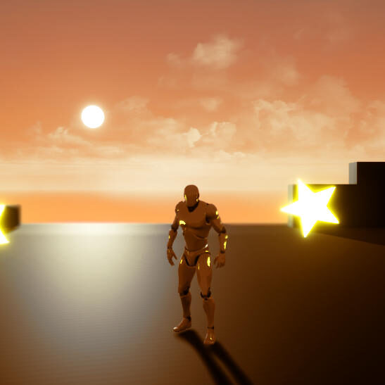
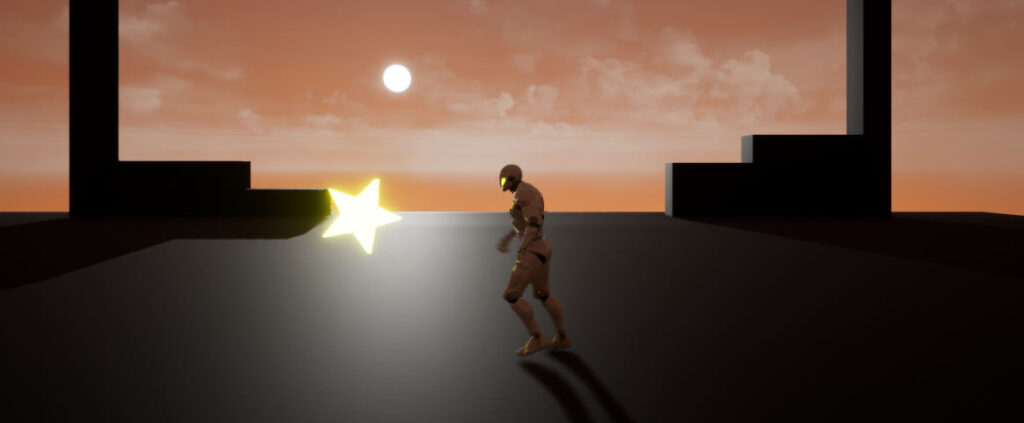
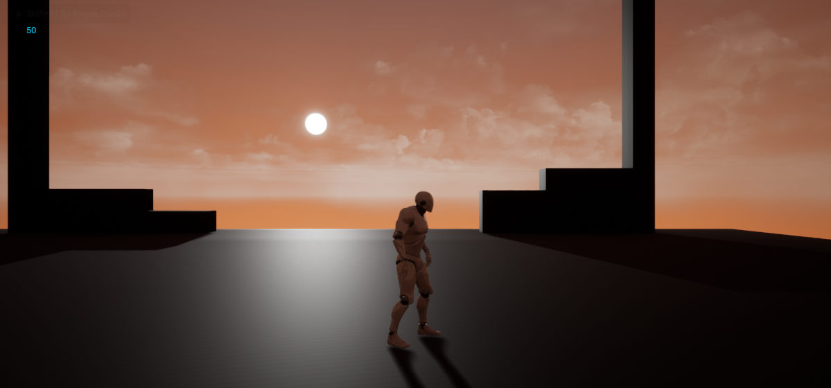
Our objectives for this phase of developing our game are quite simple as the main outcome remains focussed on a basic introduction to the Blueprints visual scripting system in order to add interactivity to elements within our game. We will continue from our previous post on developing the StarPickUp asset, the outcome from the perspective of the player is that when the character passes through the StarPickup it should disappear. At this point int time, a relevant value is added to the player’s score and this is reflected on the screen, during gameplay. At present, when the player attempts to pass through the Star pickup they are prevented from doing so. This is the default behaviour of UE4, that being the StarPickUp Actor has an invisible collision box surrounding it which is preventing the player (Pawn) from passing through it.
Our process for adding the required interactivity follows,
- Detect if the Pawn is colliding with the Star Pickup Actor
- If so, add a corresponding value to the Pawn’s Score
- Destroy the Star Pickup Actor
- Update and display the Player’s score
Transferrable Knowledge in Working with Blueprints
In order to add the necessary functionality to our Blueprint open the StarPickup’s Blueprint editor. We are going to start by creating some very basic behaviour, that will allow the player to pass through the Pickup. At that point, the Pickup will be destroyed (removed from the game).
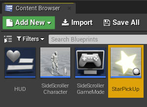
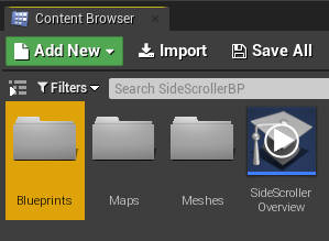
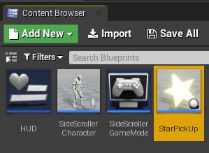
Open the Blueprints folder in the Content Browser and double-click the StarPickUp asset to open its Blueprint editor. Bear in mind we are not editing the Static Mesh asset directly, which would typically be located in the Meshes directory within the Content Browser. The Static Mesh actually forms part of the StarPickUp Blueprint Class.
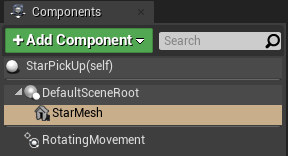
Once inside the Blueprint Editor, select the Static Mesh (StarMesh) in the Components panel (on the left-hand side of the Blueprint Editor Interface).
There are various types of Blueprints that we can create but a Blueprint Class (also simply referred to as a Blueprint) will be the most common we will use throughout this series and for many other game projects. If you are familiar with the Object-Oriented programming paradigm the term class is used very much in the same context.
You can think of the class that we are currently working on as something that retains all that is necessary in describing how the pickup will eventually work in the game world. Once we have completed work on our class and we are ready to use it in our game, we will drag copies of it into the 3D viewport from the Content Browser. In fact, the objects (or Actors) that we place in the 3D viewport can also be referred to as instances rather than copies. They are instances because they inherit all of their meaningfulness, and whatever is required to make them work as expected from the class that we designed and any changes we make to the class will be reflected in all of its instances.
Depending on how you design your class, the instances of the class can have various different properties for example each StarPickUp that is instantiated from the class will have a different position. You could even design them to have different colors or different values equating to higher or lower scores when the Player passes through them. So although they all come from the same class, their purpose within the gameworld might differentiate.
As you can imagine, bearing this in mind, the visual scripting language’s namesake, Blueprint, is no coincidence. When we create classes we are effectively creating blueprints that describe how the objects that we use within the game world will work and interact with other game elements.
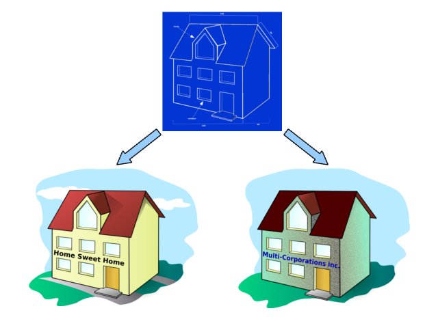
If this concept is somewhat difficult to grasp you could think about it in the context of a blueprint for a building. The blueprint contains all of the necessary information for creating the building, however, the blueprint itself is not something you could live in. It’s simply there to describe the possible outcomes. When you create a building from the blueprint, that becomes the useful object, in the same way, that we instantiate Actors from the blueprint class in UE4 and place them in the game world. However, it’s also worth remembering that not all objects are necessarily equal. For example, using the same blueprint one building could be used as a home while another could be used as an office.
Although C++ did not have the first implementation of Object-oriented programming, the language certainly has done a lot to popularize the programming paradigm as we see many different high level languages supporting it. You certainly don’t need to understand Object-Oriented Programming (OOP) to work with Blueprints, but if you ever wish to take things a little further by integrating your blueprints with custom C++ a basic understanding of OOP can certainly go a long way.
Collission Detection and Reaction Setup
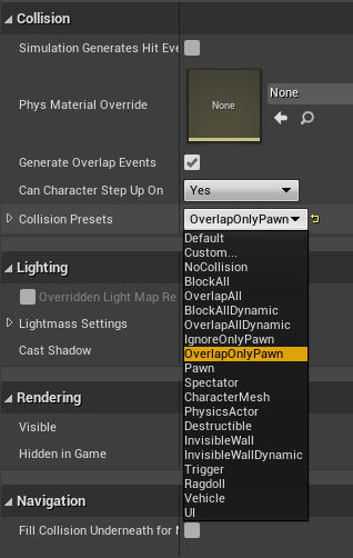
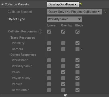
In the Details Panel (on the right-hand side of the Blueprint Editor) look for a section called Collision. You will find a drop-down list for Collision Presets. These presets setup quick configurations when a collision occurs with the selected component.
Select OverlapOnlyPawn from the options. This setting will allow for actions to be triggered when the Pawn collides with the StarPickUp Actor.
Below the drop-down list you can see a set of options that are effected by the choice you have made. You can also choose Custom to determine your own configuration.
As no physics are required in order to trigger the necessary action that will destroy the StarPickUp that the Pawn is colliding with you will notice that the collision is enabled with a Query only. This can save some valuable computation resources.
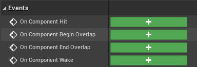
In the Details Panel, scroll down to the section called Events and click on the + (plus button) to modify the Event Graph for the On Component Begin Overlap event.

You will then be taken to the Event Graph (in the middle of the Blueprint Editor interface). The Event Graph is where the concept of the visual scripting interface really comes to life. The Event Graph represents various events that are triggered during gameplay and therefore provides a visualization of much of a game’s interactivity.
When the Event Graph is loaded the On Component Begin Overlap node will automatically be added. This is a result of entering this interface through the Events section of the Details Panel (as previously noted).
Understanding Nodes
Nodes provide the core visualization of data that forms the scripted element of a game. They can be made up of various types of data, perform various functions and can be used to construct countless programmatic statements. In Unreal Editor you would typically access Nodes for creating and modifying Blueprints through the Graph Editor within a tab such as the Event Graph (which we are currently using) or the Construction Script.
The Graph Editor (within the Blueprint Editor) is used to edit the Nodes that form the currently selected element’s Event Graph. The Event Graph is a node-based visualization of the code that will typically be executed for the currently selected element. For example, when gameplay begins the Nodes within the Event Graph will be executed for the StarPickUp Actor, thereby defining that Actor’s interactivity within the game world. How the Nodes are executed, will depend on how you have constructed the graph.
Constructing an asset’s Event Graph can be very straight forward or exceptionally complex however there remains some basic features of the Event Graph that are consistent across simple to complex systems.
- The Event Graph for an asset consists of Nodes
- Nodes are typically connected to each other
How Nodes are connected to each other will depend on what you are hoping to achieve but again there are some very basic rules that apply across all systems and thereby make it somewhat easier to learn how to create an assets Event graph.
Nodes are represented as a block with a heading (the name of the node) and one or many pins. The pins of a Node will be of various colors but there are essentially only two different types of pins.
- Executable Pins
- Data Pins
Both Executable and Data pins can be either an Input or Output pin. Whether the pin is an input or output does not change the type of pin it is, it simply determines how data enters and exits a node through it’s available pins. All input pins are aligned to the left side of the node and all output pins are aligned to the right of the node. You might have noticed that the On Components Begin Overlap node only has output pins, nodes can consist of either or both (depending on the node in question).
Nodes can be thought of as programmatic statements and the order in which these statements are executed is determined by the connections between Nodes, via their pins.
Executable Pins
Bearing this in mind, a Node’s Executable Pins represent this concept implicitly. Executable pins appear on a node as somewhat arrow shaped and it is this arrow that points towards the order of execution.
You can connect node’s Executable pins and thereby determine the order of a scripts execution, by clicking and dragging the output executable pin of one node and dropping it onto the input executable pin of another node.
Data Pins
However, what about when you want to pass data as a result of a node’s execution from that node to another node? That is when you would need to use a Data pin in conjunction with an Executable pin. How you pass data from one node to another matches the same sequence as connecting executable pins, that is, to connect the output of one data pin to the input of another data pin on another node. However, when making the connection between data pins there are several other factors to take into consideration.
Not all data pins are compatible with each other. Data pins are all of a particular type, and it may not be possible to convert data of one type into another. A pin’s different data types are all color coded and it is safe to assume that in most instances connecting an output pin to an input pin of the same color type will result in a valid connection. Some of the data types we will use most often follow,
- Red Pins – represent boolean data which will typically have a value of true or false
- Light Blue Pins – are of type integer, otherwise known as a whole number (0, 1 , 2, 3 etc)
- Green Pins handle Float values or numbers with a decimal point (3.174 etc)
- Pink Pins are used for Strings, in other words, literal characters that don’t need to be evaluated within mathematical expressions in order to return a value. Often strings will contain letters of the alphabet for example “This is a string value” and so it this “1234abcd”.
Of course, there are other data types, but for the purposes of what we are setting out to accomplish an understanding of these four will be more than sufficient for now.
Destroying the StarPickUp
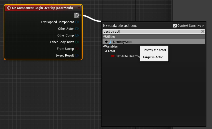
There is more than one way of creating and connecting nodes within the Graph Editor. By clicking and dragging anode’s output executable pin a wire will appear. These wires represent the links between data and executable pins. When two nodes are connected they are said to be “wired”.
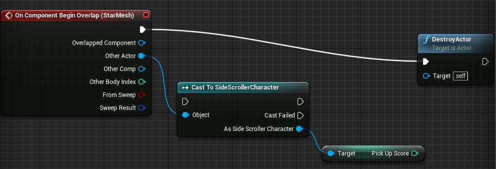
When making a connection in this way the node you wish to connect to does not need to exist prior to dragging the output pin, simply drop the pin on an empty area of Graph Editor and a context sensitive menu will appear. From this menu you can search for the node you wish to create a connection with, by it’s name. In our case the node we would like the executable pin to connect to is the DestroyActor node. Type in the name of the node and select it from the list of options.
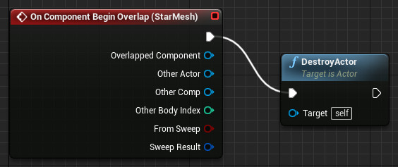
The Editor is smart enough to know that you intended to create a connection between the output executable pin of the On Component Begin Overlap node with the the input executable pin of the DestroyActor node. It will subsequently wire the nodes correctly for you.

Once you have the Event Graph for the StarPickUp created, Compile and Save the changes. Then close the Blueprint Editor and test your game. Now when your Pawn collides with the StarPickUp, it disappears and the Pawn is free to continue running.
A Network of Nodes
Although we are moving in the right direction, we are not quite there yet as we currently have no score system that is able to track how many pickups our player has collided with and, as a result, what the player’s score is.
In order to accomplish this we will need a slightly more complex network of Nodes to replace the Event Graph we currently have associated with our StarPickup. Don’t worry though, because although the setup we will be replacing our existing Event Graph with is more complex learning the logic and how to apply this understanding is fundamental to developing many different types of interactions for games. As a result, if you can understand the logic you only need to learn it once then adapt this approach to developing a variety of different types of interactions within your games.
There are a couple of tasks we will need to perform when creating our new node network,
- Add a variable to our pawn
- Access/Get this variable from the StarPickUp actor
- Manipulate the value
- Then return/Set the value to replace the old value
- Display the new value during game play
In other words we are going to get and set a variable, this is one of the most fundamental concepts of programming.
Working with Variables

Once you are satisfied with your results, End the game and go back to the Content Browser. We will first need to add a variable to keep track of the player’s score. We will add this to the Pawn. Double-click the SideScrollerCharacter to enter it’s Blueprints editor.
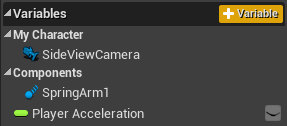
Under the Components section, you will find a section called Variables. Variables are used to store information. This information can be a number, a string of text, a group of different values or various other types of data. As we would like our variable to keep track of the Player’s score our variable will be a number, more specifically our variable will be an integer data type. Integers are whole numbers like 0, 1, 300, -2 etc as opposed to floating point numbers which are numbers with a decimal place eg 2.12, 45.1, 78, 0982. As previously mentioned it’s considered best practices not to mix different types of data. However, as we will see a bit later through the process of casting, this can be possible. Bear in mind, though, casting can come at the expense of some additional computational resources (and perhaps bad practices too).

Click on the +Variable button to create a new variable attached to the currently selected character. Name the variable PickUpScore.
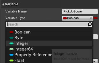
In the Details panel a section for editing the variable will now be available. Your new variable’s name will be displayed as well as it’s data type. As previously mentioned we will use the variable to keep track of our player’s score and as a result we will need this variable’s data type to be a number. As we will not be concerned will decimal numbers our variable data type will be integer. Click on the drop-down list and change it from the default value of boolean to integer. It’s worth noting that using integers when possible over floating point numbers can contribute to better managing a system’s resources, as with a float (as they are sometimes called) you would be concerned with precise values therefore more numbers are required for this accuracy. This could essentially result in more memory usage, unnecessarily.
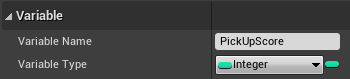
Your new variable’s description should now currently look like something in the image.
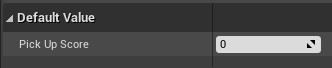
We are going to initialize our new variable with a default value of zero. This makes sense as you would like your player to start with a value of 0 when the game starts and hopefully increase their score as they progress through the level.
In the Details panel you will find a section called Default Value, where you can specify the starting value of the variable. If you are unable to add the default value, then you will first need to Compile and Save your Blueprint before proceeding. Once the blueprint has been compiled the variable will now be accessible not only from the current blueprint editor but from other game elements too. This is significant as we will need to access this variable from the StarPickUp when a collision is detected between the pickup and the pawn. We can then modify the variable via the StarPickUp blueprint.
Creating the Scoring System
We will be adding the functionality that adjusts the player’s score to the StarPickUp. This makes sense as we will use the collision detection that we previously setup between the pawn and the pickup (that made the pickup disappear), to access the pawn’s variables, set a new value and replace the old value with the new value on the pawn.
If you are finding it difficult to visualize what we are doing, you can think of it in terms of the player holds the score and the pickup determines what to do with the score.
Double-click the StarPickUp to enter it’s blueprint editor. You will see that the previous Event graph we set up to destroy the pickup will be visible. We are going to modify this graph to include the functionality that updates the score before destroying the pickup.
We are going to start by getting access to the variables associated with the SideScrollerCharacter.
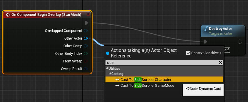
Click and drag the Other Actor pin to an empty space in the graph editor and drop the pin. Within the context sensitive menu start typing “sidescrollercharacter” (spaces and casing are not particularly important). Select Cast To SideScrollerCharacter from the menu.
Getting
A new Node appears with the relevant connections already wired. This node allows you to access other actors from the currently active selection. In our case the active selection would be the StarPickUp and the actor we are trying to access is the SideScrollerCharacter. By casting from our current blueprint class to another actor we can do things such as access data and functionality of the other actor, then use the results in our currently selected blueprint. This is precisely what we will be doing.
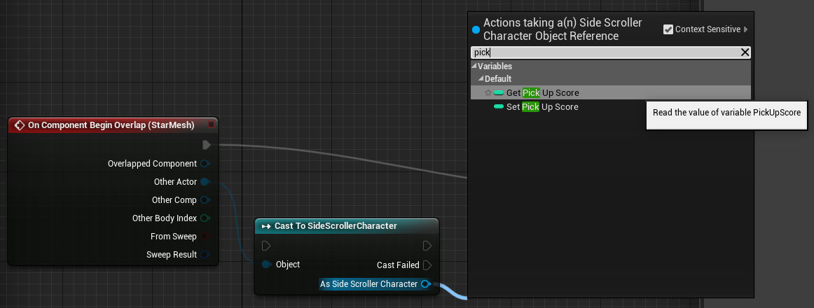
Click and drag a pin from As Side Scroller Character start typing the name of the variable (“pickupscore”), we created in this actor (our pawn). Options to Get and Set the variable will appear. We are, of course, first concerned with getting the variable and only later setting it once we have updated it’s value.
Select Get Pick Up Score from the menu options.
Once you have the new node wired your Event graph should like the image.
We are now going to perform some simple addition on the value that we just retrieved. Before continuing it might be a good time to reiterate on what we are doing. Now that we have access to the PickUpScore variable we are going to add a number to it, this number represents the value that the player’s score is incremented by each time they pass through a pickup. By getting the value that is set on the player we can augment that value with another integer. Therein resides the significance of why the value must be a variable and why the integer being added to it, does not need to be a variable.
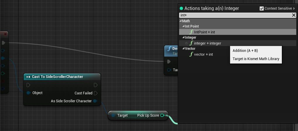
In order to add a number to the PickUpScore variable, click and drag the Pick Up Score pin from the Get node and type “int + int” in the context sensitive menu. Select the integer + integer node.
You should now have an Event graph that resembles the image. The integer + integer Node has two input pins the first should have automatically been wired with the output from Pick Up Score, the second input is the value (number) that will be added to the first. You could specify another node as the input value or simply type an integer into the input field. As the value we are incrementing our score with does not change, we will simply input a number into the input field.

We now have a new number, that being the value that increments the players score plus the previous value of the players score. In other words, if our player’s score was 0 and we incremented it by 25 with the integer + integer node our expression would look something like 0 + 25. Therefore our new value would be 25. The next time a player passes through a pick our expression would look different, for example, 25 + 25 therefore the value would be 50 and so on.
At this point in time, the expression is being calculated but the result is not being stored for further use. As you can imagine the result should be reflected by the original variable PickUpScore, as we are ultimately performing this calculation to determine the players score. Bearing this in mind, we are now going to assign the new value back to the original variable after the calculation has been executed. Just as we obtained the variable in order to get it’s value we will follow a similar procedure in order to set its value.
Go back to the Cast To SideScrollCharacter node and from the same pin that you used to obtain the PickUpScore variable (As Side Scroller Character) drag another pin and again start typing “pickupscore”. However, this time choose Set Pick Up Score form the menu.
Setting
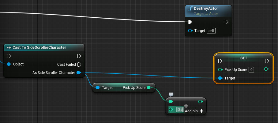
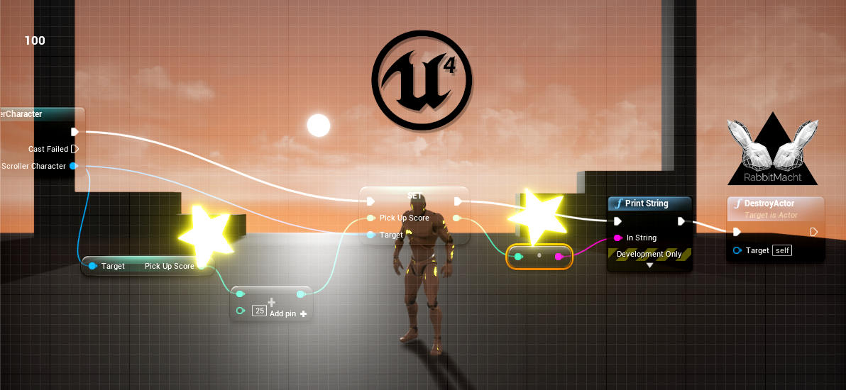
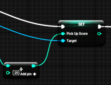
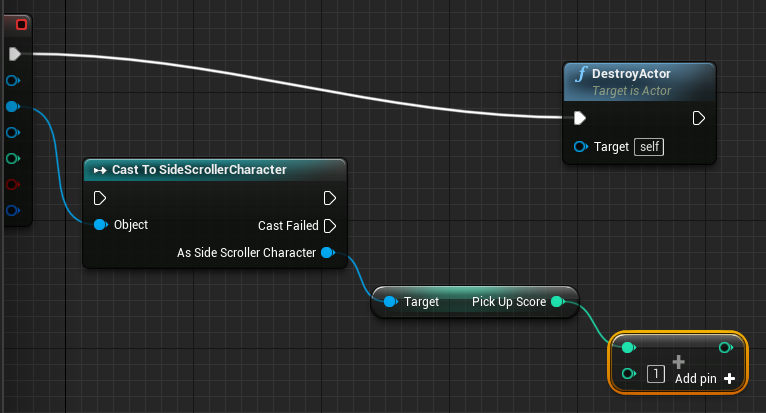
You will notice that the Set Pick Up Score node has three input pins, one executable pin and two data pins. Just as with the Get node it has a Target pin in order to retrieve the necessary information from the actor. A Pick Up Score input pin also exists that allows you to type in a specific value to set the variable within the input field or you could use another node to set the value dynamically. Of course, the latter is going to be what interests us. To reiterate we are setting the value of the variable dynamically from the integer + integer node.
In this example the second value of the integer + integer node has been set to 25.
Drag the output pin from integer + integer to the input pin of the set node’s Pick Up Score value. We have updated the PickUpScore variable on the SideScrollerCharacter with the value that has had the expression applied to it. To recap first we get the value from the actor, then we manipulated the value, and finally we returned the result back to the original variable, thereby setting the variable.
We have now completed the necessary mathematics operations in order to get our scoring system started. However, if you were to test the game at this stage there would be no visual indication of all of our hard work we just performed for two primary reasons. Firstly, and most importantly, although the code works (and you can verify this by clicking the Compile and Save buttons), it is never actually executed.
If you were to follow the flow of the script’s execution from the point at which the collision between the pawn and the actor (i.e. the SideScrollerCharacter and the StarPickUp) occurs, you will notice that it goes straight to the DestroyActor Node, thereby bypassing all of the new modifications we made to the graph.
In order to fix this we will need to disconnect the wire with DestoryActor and place that node at the end of the chain, after get and set have been executed.
Alt-click the execution wire going into DestroyActor’s input executable pin. This effectively deletes the wire but leaves the node intact.

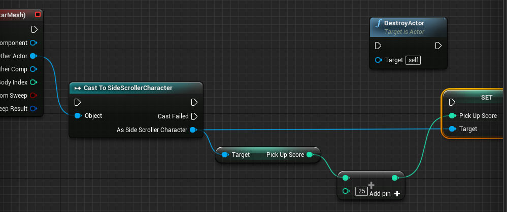
Now that the executable output pin from the On Component Begin Overlap node is available again, click and drag the pin to the input executable pin of the the Cast to SideScrollerCharacter node

In following a logical flow of execution, click and drag the output executable pin from the Cast To SideScrollerCharacter node to the input executable pin of the Set node. As you will notice, in order for the Set node to complete execution, first the Get and Integer + Integer Nodes are executed. Subsequently, there is no need for these nodes to have executable pins.
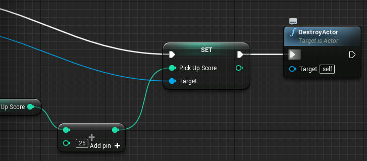
Finally, reconnect the DestroyActor node to the end of the event graph by setting it’s input executable pin to the output executable pin of the Set node.
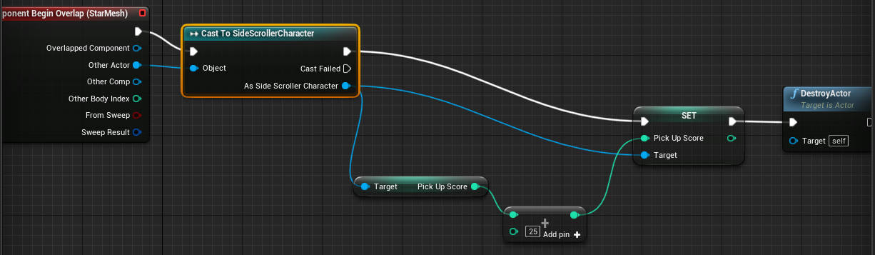
Your new event graph is now completed and it should look something like the image. Click Compile and Save before exiting the Blueprint Editor.
Debugging Tools
If at this point you were to test your game you would still not see any visual representation of the player’s score. However, this time around although you cannot see a difference, there is in fact, a fundamental difference to the game’s scoring system in that the code will successfully be executed.
Debugging in terms of software development relates to the process of removing errors and faults in a codebase. However, some errors might not necessarily be clearly visible when running your codebase and as a result, many development toolkits (Unreal Editor included) will provide tools to assist with this process, by exposing parts of how your application is running and if it’s performance is matching your expectations.
One of the debugging tools available to us in Unreal Editor is the Print String node. This node has the ability to display text while the game is running. As this is a debugging node, the text will only be visible while the game is run through the Editor, in other words debugging information is not (and should not) be retained when the game is built for a specific platform.
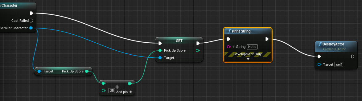
Lets go ahead and again delete the execution wire connected the Set and DestroyActor nodes. Although, the process we have taken of connecting and disconnecting nodes my seem unnecessary it is in fact very common to work like this within the Events Graph as you experiment with new functionality and change existing graphs. Drag an executable output pin from the Set node and start typing “printstring” select the Print String option and connect it’s output executable pin to the input executable pin of the DestroyActor node.
The Print String node has a data input pin called In String. By default this is simply set to a text value of “Hello”. This is basically what will be displayed during game play for the purposes of debugging and as you can image this is not presently particularly helpful for us. We would ultimately like this node to serve the purposes of printing the players score during game play and while in debugging mode.
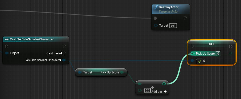
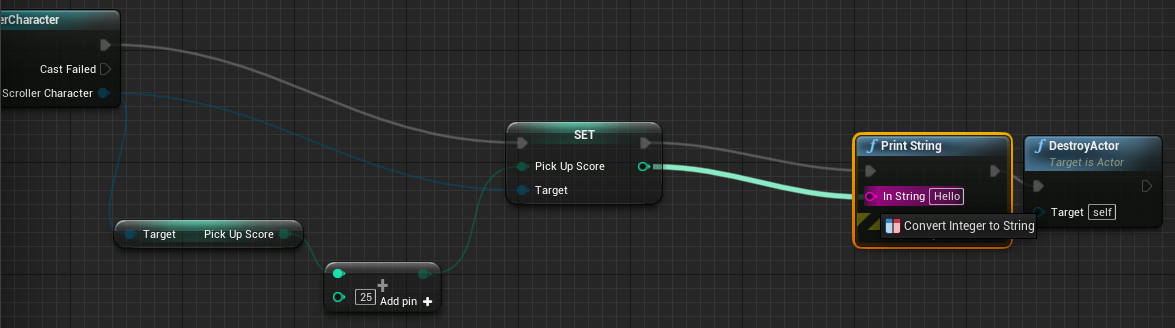
We will need this value to be updated dynamically and as a result, we will use the Set node to update the value. Click and drag the output pin of the Set node’s Pick Up Score property. Drop the pin on the input In String pin of the Print String node.
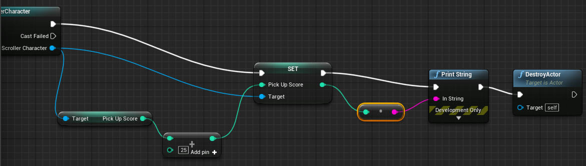
When hovering this pin over the In String pin you will notice a message appear saying Convert Integer to String. As previously noted data pins are color coded and you might have noticed we are mixing colors here as we are attempting to connect an integer data type with a string data type. Fortunately in this case it is possible to do this as when you drop the pin the Editor creates an auto-casting node. This node performs data type casting (conversion) from an integer to a string, in this case, for us.
Compile and Save the blueprint before exiting the editor.
The result is that now when you play the game your character can pass through a pickup, the pickup is destroyed and just before this happens the players score is updated and displayed (for debugging purposes) in the viewport.
Coming up
If you have worked your way though the entire series then you have accomplished quite a great deal in terms of getting to grips with a fundamental understanding of working with Assets and the Blueprint Editor to create interactivity with your games.
In the next post we will be looking at developing a health system for the game, as well as adding assets with animation within our game and converting the debugging information to something more useful that our players can see.
- Starting out with Vue : Part 1
 What is a Software Framework A software framework provides a level of abstraction in writing application code relevant to an environment.Although this may sound like a mouthful, it’s quite simple when you start to unpack it. When we write code with JavaScript we are utilizing its environment to provide a context for our software and… Read more: Starting out with Vue : Part 1
 - How To Secure Your Site With HTTPS For Free
 Although HTTPS has been a standard web protocol for some time many hosting providers still do not necessarily provide support for enabling it “out-the-box”. In this post, we will dive into the details around setting up HTTPS for your website using a completely free set of tools and also discuss some basic concepts around what… Read more: How To Secure Your Site With HTTPS For Free
 - A Super Versatile Minotaur, Rigged And Ready To Rumble
 Lets dive into the details on the Minotaur character that has recently been published by RABBITMACHT. In this post, we are focusing on how you can incorporate The Minotaur 3D Digital Asset into your own projects by exploring how this character is built and effectively leveraging these resources in your own workflow. The Minotaur consists… Read more: A Super Versatile Minotaur, Rigged And Ready To Rumble
 - How To Build Game-ready Characters With A Non-destructive Workflow
 When developing 3D characters it’s important to retain as much of a non-destructive workflow as possible. This is particularly important with regards to games development as the models used in the final output will often have certain elements baked into texture maps. Without a non-destructive workflow, modifying a baked a texture map or rebuilding components… Read more: How To Build Game-ready Characters With A Non-destructive Workflow
 - Immediately Start Selling, with the Starter Store for Curated Merch
 Although 2020 may have been a tough year for many of us, that doesn’t mean we should be down and out about it. Some industries have even experienced growth in the time of the Corona Virus Pandemic. In particular, if you work in the e-commerce industry you might have encountered many client’s growth last year… Read more: Immediately Start Selling, with the Starter Store for Curated Merch