
UV Layout
Students I’ve worked with have often asked me why the term UV is used? And the answer I give them is the same answer I was given 15 years ago when I was learning about UV’s for the first time. “The term UV is used because it is not XYZ” As ambiguous as that may sound, it is probably the most fitting description for UV’s that I’ve ever heard.
As with the term XYZ in 3D UV’s also relate to dimensions, but as you can imagine U and V relate to only two dimensions. Although it is not a given rule, most 3D applications will use the U dimension to represent width and V to represent height. But U and V dimensions are not simply 1 to 1 pixel matches relating to the width and height of a bitmap image. They are in fact used to quantify “texture space” which comprises of 2 dimensions. As you are aware textures are 2 dimensional bitmaps, procedural maps or other map types that are wrapped around a 3D object. UV’s provide the crucial method by which texturing and mapping artists translate these 2 dimensional maps into a 3D environment.
In much the same way that a vertex represents a point on a 3D model in 3 dimensional XYZ space, a UV represents a point on a 3D model translated into a 2 dimensional texture space.
When you view a Bitmap used as a texture for a model in a 3D application’s UV editor it will be forced to fit into a square shaped editing area, this area is often referred to as 0 to 1 texture space. This simply means that the square area is used to measure a starting value of 0 (at the UV texture space origin) to a value of 1 in both the horizontal and vertical axes in floating point numbers. As the amount being measured is the same in both dimensions (i.e. 0 to 1) the area forms a square shape, and is as such referred to as 0 to 1 texture space. The bitmap that you create to use as a texture and subsequently (with the aid of UV’s) intended to wrap around your 3D model, must fit within this texture space.
Various 3D applications have different methods for achieving this, and as such it is important that you try to avoid letting your 3D software decide how to make your bitmap fit into this square space. The most obvious method of achieving this is to create bitmaps that are square, in other words the bitmaps width must match it’s height. Furthermore, in order to make efficient usage of your machine on which the rendering (real-time or pre-rendered) of which these textures will be done the dimensions should be to the power of 2’s for example 16 x 16, 32 x 32, 64 x 64, 128 x 128, 256 x 256, 512 x 512, 1024 x 1024, 2048 x 2048, 4096 x 4096 etc Using bitmaps that have dimensions that are to the power of 2 will also be particularly useful for graphics displays that use the mipmap technique for displaying textures.
You can read more about UV mapping in my “Understanding UV’s” page.
UV unwrapping should only be attempted after the modeling phase is completed. Edge loops need to represent the models target topology, as the key points to creating a good UV layout is in creating a layout that:
- Matches the models form as close as possible
- Does not have overlapping UV’s
- Minimizes stretching
- Uses texture space as efficiently as possible
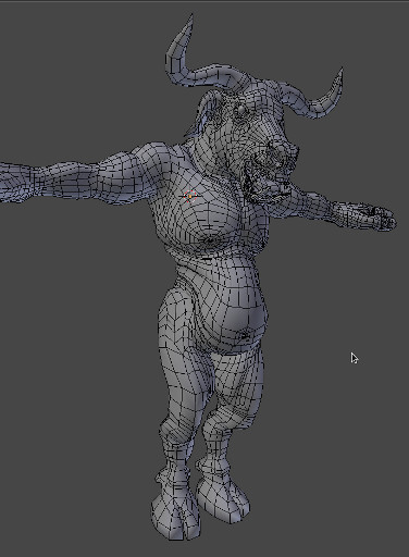
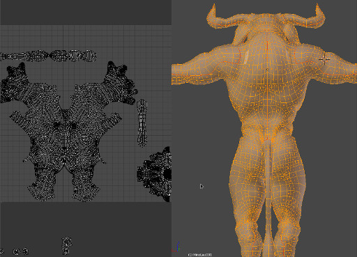
UV editing has come a long way since it’s first implementations. Certain areas of the mesh need to be isolated as they will require extra detail or form separate pieces of the same model. One of the major advancements in UV editing is automatic unwrapping. The first implementations that I used of this was in a 3D Studio MAX plugin called “Pelt”. As you can see the map on the left of the above image is starting to resemble what the pelt of this minotaur might look like. This is what is meant by, “the UV layout should be as true to the original model’s form as possible”. From this layout we can tell by looking at it that it is from a character that has two legs, arms with fingers and a torso. These isolated UV components floating around in texture space are called UV shells.
The subtle red lines that flow through the Minotaur on the right represent the seams along which the UV shells will be separated to form the flat shells you see on the left. In other words the outer edges of the shells are the red lines you see in the 3D model.
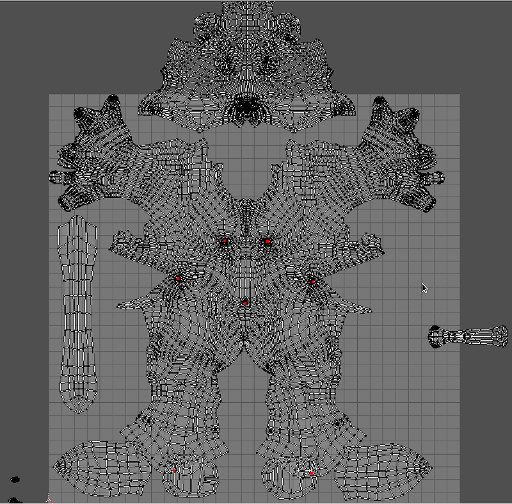
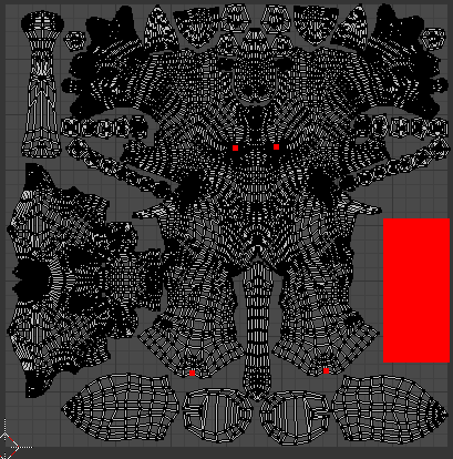
The completed UV layout in the final image. The shells are as follows corresponding to the appropriate side of the model (i.e. left ear on the left side, right hoof on the right side) starting from the bottom shells ears and hooves, tail in the middle, and the main shell consisting of limbs, torso and neck, the head is to the left (and is the second largest island), rows of teeth molars (lower jaw, upper jaw) on either side of the main shell. The buckle cavity (mouth interior) in the upper left corner, with major canines on the top of the layout and the tongue in the middle.
The red area on the right is an empty space for the eyes which will eventually be joined to this mesh. But only after sculpting is completed, this is to reduce the amount of geometry that will be subdivided when sculpting the face.