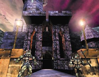
Although the source code for Unreal Engine has been made freely available in more recent times, creating and editing levels using the engine is nothing new. In fact, since the first game that used the engine in 1998, that being Unreal was published the intrinsic link between gaming and games development has always been evident within the Epic Games ecosystem.
If you can recall that far back one of the most impressive elements of Unreal was in UnrealEd, a level editor that was distributed at no extra cost to the game. However, let’s not forget the original games beautiful lighting, compelling gameplay and that incredible fly-by intro sequence that sets the tone for all the mystery and intrigue that is to follow.
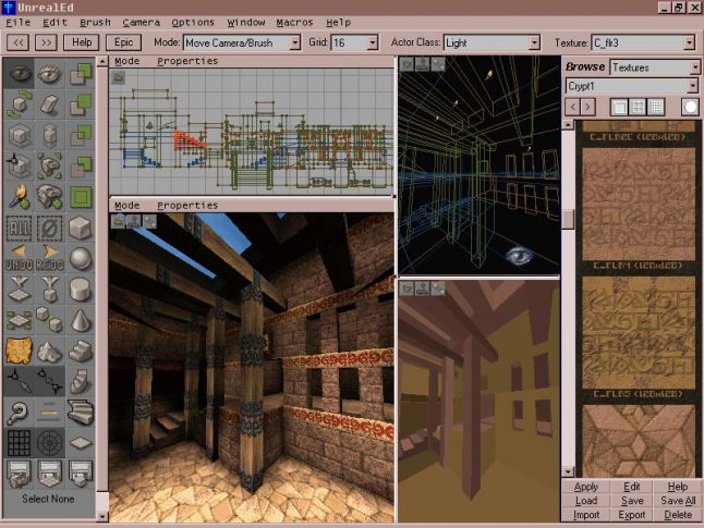
The Unreal Engine has progressed significantly since it’s initial inception of UnrealEd, in this post we will be setting up Unreal Engine 4, currently the latest version of Unreal publicly available and soon to be replaced by version 5 in 2021. Although you could easily head on over to Epic’s site and download a copy of the engine, for easy installation, we will instead be building the engine from the source code. There are many benefits to building the engine from source of which one is that we are not restricted to the Operating Systems that are supported on the official download page such as Windows. We will be building the Unreal 4 Engine on Ubuntu 20.04 LTS Focal Fossa.

Technically speaking it’s not entirely necessary to use this version of Ubuntu, or Ubuntu at all. As previously noted building from source removes such limitations so you could use just about any modern Linux-based distro. However, for the sake of convenience and simplicity, we’ll be using Ubuntu’s most current LTS (Long Term Support) version.
In continuing the Open Source ecosystem of this project we will not be relying on propitiatory Autodesk products (with all due respect). Instead, we will be utilizing the Open Source Blender 3D content creation suite to develop and import assets into our Unreal project. Of course, one of the main benefits of this approach is that to get you up and running will not cost you a dime in terms of software purchasing, licences or the like. However, it is worth noting in the long term if you do happen to make a game that does start making money then depending on how you distribute it, UE4 licensing could result in some costs.
Now that we have an idea of where we’re heading lets jump right in and get started with building UE4 on Ubuntu.
Build from source
When building a project from source code you will need to take into consideration the programming language/s used to develop that code. Without this consideration, source code is nothing but ASCII text, similar to that in a word processing document. However, in order to make something useful of the source code it needs to be converted into something that a machine can understand, this refers to the process of compiling which forms a part of the build process.
Building an application from source code will generally involve several steps but simply put in the context of what we are doing, we will
- Resolve dependencies
- Create online accounts
- Clone the codebase
- Configure resources
- Make and install from binaries

Take your first steps into the increasingly popular field of 3D animation, with this beginner course in modelling, texturing and character development fundamentals
Resolving Dependencies
Before we get started with accessing and downloading the source code there are a few additional tools we will need in order to ensure the build is successful. The process of installing the requirements needed to build an application from source can be referred to as resolving the software’s dependencies.
- In terms of UE4, the source code is written in C++ and as a result, you will need the tools for compiling a C++ application.
- As UE4 makes extensive use of hardware acceleration in order to render very sophisticated 3D graphics in realtime, you will need the latest drivers for your Nvidia or AMD graphics card. This is not as much a dependency as a software requirement, as this only becomes relevant after the application has been built.
- Finally neither a dependency nor a software requirement, but arguably an essential component within any developers toolkit would be a solution for Version Control Systems (VCS). In this case, the recommendations would be Git and GitHub.
As previously mentioned the operating system we will be using is Ubuntu 20.04 LTS. Although it might be possible to build UE4 on other versions of Ubuntu, the process is somewhat simplified on 20.04 and encountering difficulties with graphics drivers on 16.04 after successful builds or failed builds on 18.04, can prove to be less of an issue.
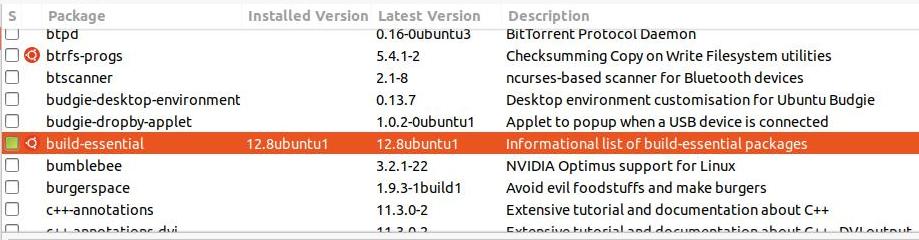
Make sure build essential is installed on your system you can do this through Synaptic or by entering the following command in a Terminal,
sudo apt-get install build-essentialBuild-essential is a meta-package, that is to say, it is not essentially an application itself as much as a tool for installing other software. In this case, the other software would primarily be for the purposes of building applications developed in C++. Among the software it will install will be g++ (the GNU C++ compiler), various development libraries as well as make, which is a utility that assists with the compilation process. Of course, you could simply install these packages individually based on your skill level and proficiency with regards to C/C++ development. If you don’t wish to install build-essential you could also rely on the setup process, noted below resolving these dependencies within the build toolchain. Nonetheless, it’s worth noting in the event you encounter difficulties or wish to expand on your C++ development skills.
You might have also noticed from the above screenshot that bumblebee is not installed on this system. After having encountered issues with the Nvidia 660M discreet card not initializing on this system, removing Bumblebee resolved the issue. If you are utilizing an Nvidia card, it is recommended that you install the latest drivers supported by that card. As a result, the system noted for this installation uses version 4.40 of the Nvidia drivers. It is also essential that you use drivers that support the Vulkan API. OpenGL and Direct3D alone will not suffice for UE4.

As you will need an Integrated Development Environment (IDE) for the purposes of developing code for your game or for editing the UE4 source code, Visual Studio Code 2017 or greater is an official recommendation. You can obtain it from Ubuntu’s Software Center, it is also available as a Snapshot.

Git is essentially a source code management tool that you would install locally on the system you will build UE4 on. Although you do not need git to build UE4 there are however some key benefits to using it, which we will have a look at shortly. To install git you could simply do so through Terminal again with the following command,
sudo apt-get install gitThis will install all the requirements for working with git through the Command Line Interface (CLI). Git forms one of the main components in working with Version Control Systems (VCS), but to have an effective solution for software development you will also need a remote hosting and VCS solution. There are several providers that can fulfil this requirement in various paid or unpaid capacities, however, GitHub is the service provider we will be using. As a result, you will need to visit github.com and sign up for an account if you do not already have one. You will not require more than a basic free account. Once you have git and GitHub setup you are ready to start retrieving the UE4 source code.
Finally with regards to accounts, make sure you have signed up for an unrealengine.com. This account is needed in order to access the UE4 source code.
Get the Source
Log into your Unreal Engine account, under your user profile you will find a link to your account settings.
Click the PERSONAL link. This section lets you customize characteristics about your account, as well as allows you to connect 3rd party software.
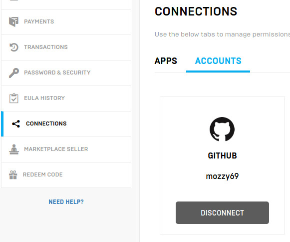
In the panel on the left is a button called CONNECTIONS
Click this button to customize what 3rd party software your Unreal Engine account can access. In this section, you will find an option to link your GitHub account. Click the CONNECT button and follow the prompts to connect your Unreal Engine and GitHub accounts. Ultimately you will need to become a collaborator on the Unreal Engine GitHub repository in order to obtain the source code. Don’t worry if you don’t have any experience with code, you will not be able to make changes to the main source code that easily. However, if your intent is to modify the source code then you should probably consider Forking the Unreal Engine source code and editing that. We’ll discuss options for accessing the code shortly, but first, you will need to finalize the connection between the accounts by visiting GitHub and clicking the Authorize EpicGames button.
Once you have authorized Epic Games access to your GitHub account, you should then receive an email inviting you to join the @EpicGames organization. This email will be sent to the address associated with your GitHub account, worth noting particularly if you are using different emails for your UE4 and GitHub accounts. Accept the invitation and you will finally have access to the Unreal Engine source code.

Now that you have access to the EpicGames repository as a collaborator when you visit their repository at https://github.com/EpicGames/UnrealEngine you will notice that the UrealEngine repo is now accessible.
Read through the Readme file, which has a friendly welcome message as well as some very useful links for learning how to use the engine.
You are now ready to Download, Clone or Fork the engine’s source code. Before proceeding there are a few suggestions that should be taken into consideration regarding these options.
- Fork: This option is particularly useful if you wish to modify the source code. Choosing to create a Fork will replicate the repository within your personal GitHub account. You are then able to modify and change the source to your requirements. This does not download the code onto your local workstation and is therefore not recommended as a standalone solution if your interests are primarily in creating games or realtime applications with UE4.
- Download: This might initially seem like the best option and although there is no particular reason not to utilize this option if your interests are primarily to get up and running with potentially as little overhead as possible, you will be defaulting on the benefits of the VCS provided.
To download the source you will first need to choose a branch. By default, the release branch is selected as this is a well maintained and tested branch with updates regularly being added and merged. If you are somewhat familiar with VCS you might be tempted to download the master branch, however, this branch is primarily the master for development and therefore not subject to as much testing as release. You can also choose to download older versions of the engine and the developer teams also have their own branches prefixed with dev-branchname. However, these branches tend to be considered as bleeding-edge and should not be used for the purposes of production as much as for development. - Clone: Cloning the source perhaps provides the most versatility in terms of the three options as this will download the source onto your local machine, allow you to modify and test your changes locally as well as benefit from working with fully-fledged VCS enabling you to do things such as checkout other branches on the same system, modify, stage, commit and push remotely if you initially forked.
git clone https://github.com/EpicGames/UnrealEngine.gitTo clone the repository navigate to the desired directory through a CLI and run the command above.
As you can see from this screenshot, cloning required approximately 3.41GiB of disc space. Depending on the speed of your internet connection this could take a considerable about of time to obtain. Although this might seem like a lot of data be aware that it is only a small part of the requirements for building and running the engine, as in order to use the engine you should have at least 100 Gigabytes of free space on your drive. That is not a typo and does not accommodate the additional space requirements of your personal projects.
Compile Binaries
At this point you would have obtained a copy of the source code, installed all the required dependencies and are now ready to start setting up the engine and installing it on your system.
To clarify, the source code you have downloaded is in a human-readable format, which makes it possible to edit and maintain. You will now need to convert this code into a machine-readable format through the process of compilation, this will result in binaries which will be executable therefore allowing you to finally launch and run the engine.
If you have followed all the steps to this point compiling the binaries will be quite straight forward and will only require a minimal knowledge of the Command Line Interface.
Open a terminal window and navigate to the root directory of your UE4 source code. You can do this by changing to the appropriate directory.
cd UnrealEngineThen run the Setup shell script. This step might take some time depending on your system’s configuration as it will download a native toolchain that will ensure the UE4 codebase compiles and links successfully on your system.
./Setup.shYou will then need to generate the Unreal Engine project files, once setup has successfully completed.
./GenerateProjectFiles.shFinally you will need to run make to build the binaries
makeThis step will require substantial system resources and time depending on the target machine you are compiling against. You will need at least 8GB of RAM and a multi-core processor (8 or more) to complete this step in an hour or less. Once this step has successfully completed and no errors have been returned you are finally ready to launch the Unreal Engine 4 Editor. Congratulations!
Launching the Editor
Well done for getting this far, it’s now time to launch the Editor and start your journey towards learning how to make your first game. Navigate to the directory where the binaries were created and launch the editor.
cd Engine/Binaries/LinuxNow launch the editor.
./UE4EditorThe first time you launch the editor, it will need to compile shaders which will take some time but fortunately, this only needs to happen the first time the editor is launched.
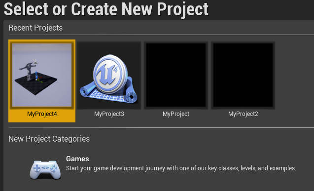
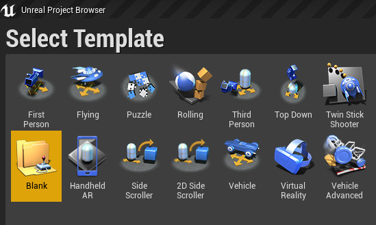
At the Create New Project screen, select Games then Next and you will be presented with the Select Template screen. Choose Blank Project, then make sure Blueprint is selected and No Starter content is required as we will be importing our own mesh from Blender.
Blueprint is the Unreal Engine visual scripting language. With it you can create gameplay through a node-based system using simple drag and drop techniques to create connections between nodes in the editor. This means that as a designer you are not necessarily limited to having to learn a programming language in order to develop your game.
Importing a Mesh into the Editor
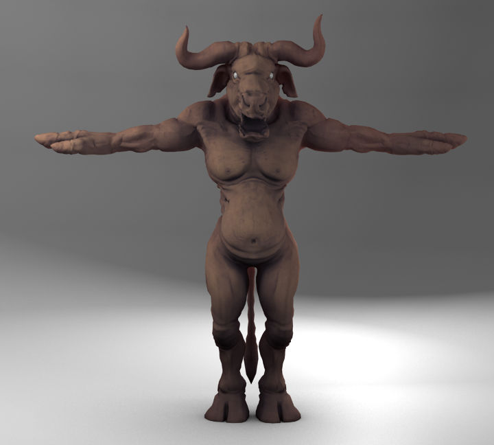
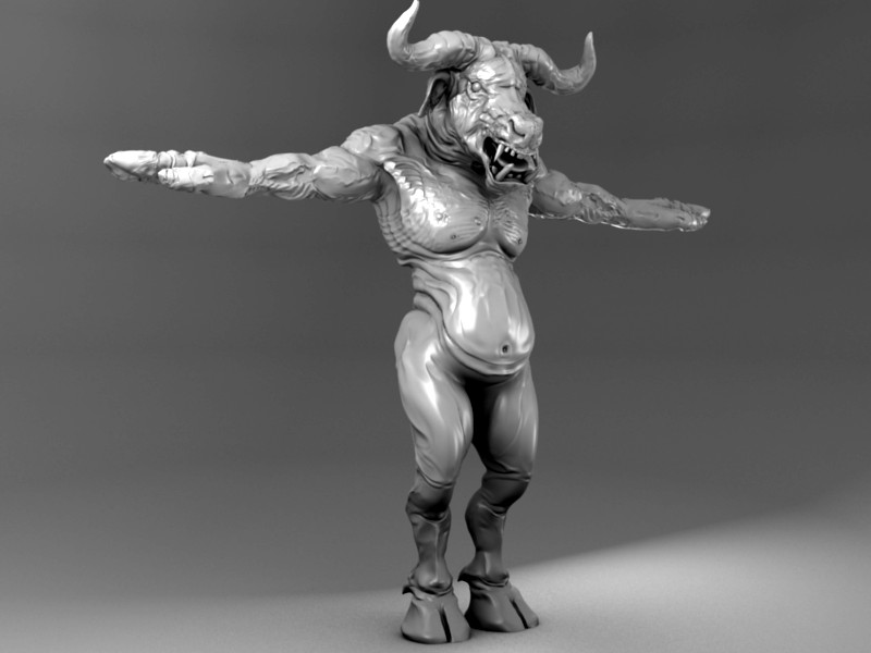
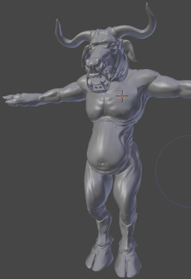
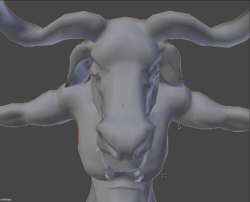
Now that we have UE4 up and running on Ubuntu we’re going to use Blender to export a 3D asset that we will import into the editor. In the interest of keeping things simple for now, we are just going to discuss the basic concepts of importing a static mesh.
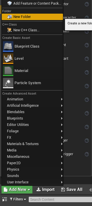
Within the Editor locate the Content Browser section in the bottom half of the screen and click the Add New button.
Click New Folder to create a new folder within the project, that will be used to store the imported asset.
You will need an asset to import into your project. There are various options for importing 3D meshes into UE4, although the official file format for this is usually considered to be FBX. The FBX file format supports animation as well as many other features, but we are just using it to familiarize ourselves with the import/export workflow.
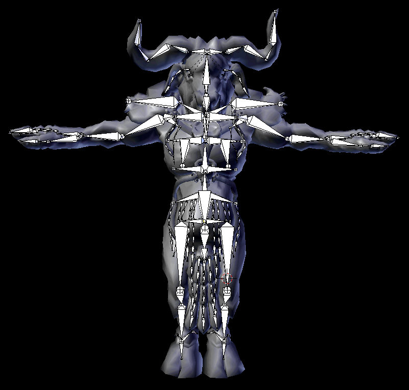
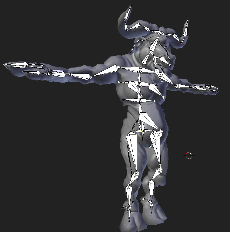
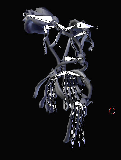
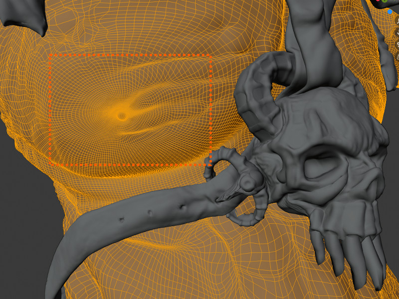
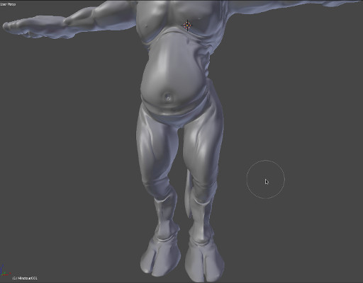
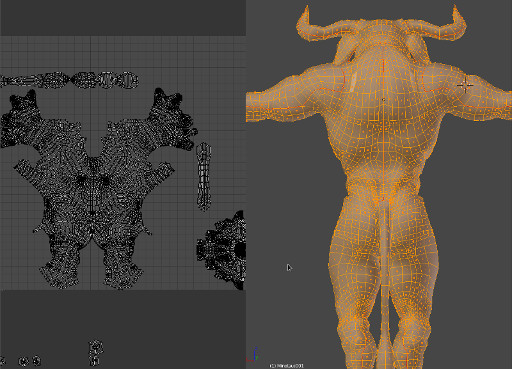
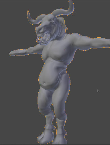
In order to prepare your mesh for exporting from Blender make sure that all transforms have been applied. In other words if your mesh has any rotation, translation or scale attributes these will need to be baked into the mesh so that your mesh transforms are all zero. If your object moves while trying to Apply it’s transforms you might need to enter the object’s Edit mode select the object’s vertices and then translate the object back into the correct position. Essentially your object’s Center of Mass should be as close as possible to the origin without intersecting the ground plane.
Apply the object’s transforms by selecting the object in the 3D viewport, then clicking the viewport object menu and Applying all transforms from the Apply menu.
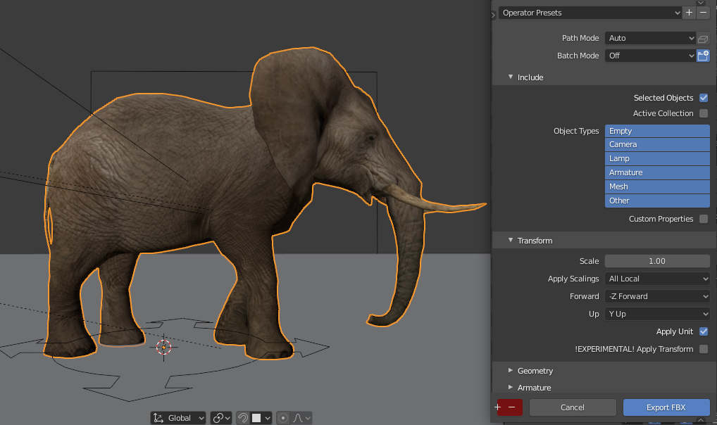
Next export the mesh by choosing FBX from the export options.
The default settings are ideal for the purposes of what we are doing, and the only option you would need to change is to ensure that the Selected Objects option is checked from the FBX export settings. Save your exported mesh and it’s time to import it into the Unreal Editor.
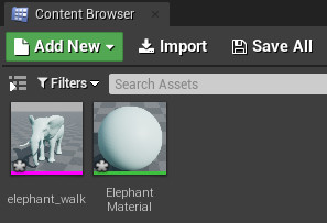
From the Content Browser in the Unreal Editor click the Import button, to import the FBX file you just exported from Blender.
When importing this file again accept the default settings. If all goes well your assets will now appear in the new project folder you previously created.
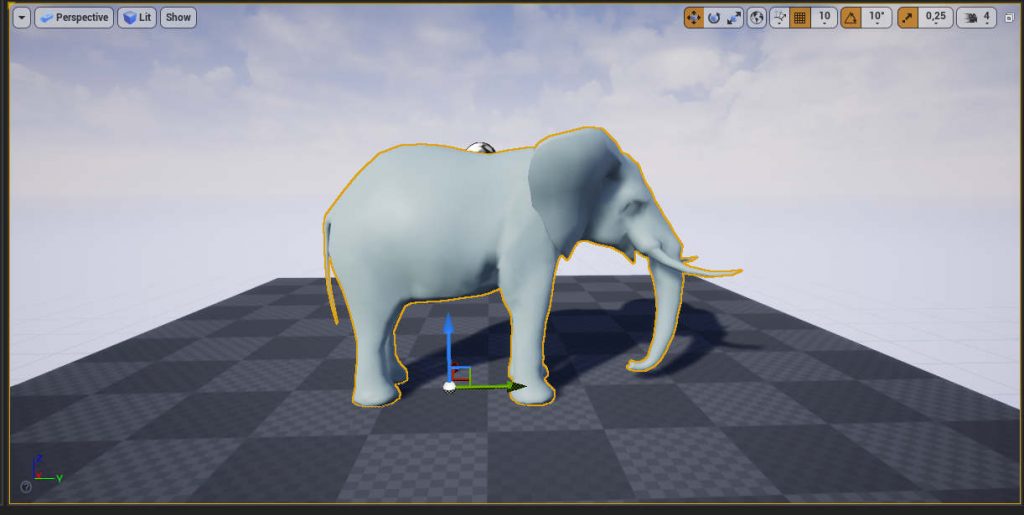
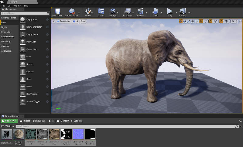
In completing this final step you would have successfully imported your 3D model into the Unreal Editor. From the Content Browser click and drag your asset into the editor viewport. Your model is now visible within the Unreal 4 3D rendering engine’s editor. Click the Play button to preview what your asset will look like in-game.
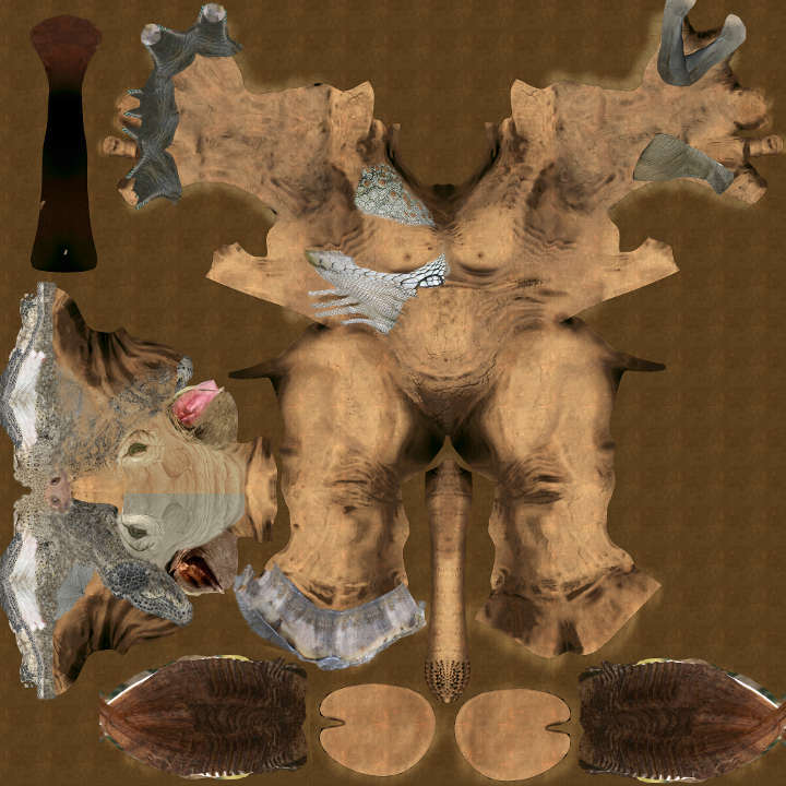
With the techniques you have learned here try import other models as well as other types of assets including texture maps.

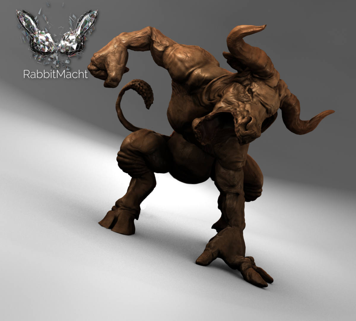
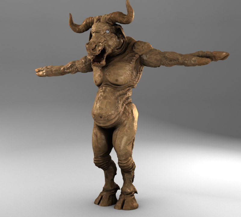
Visit the Asset Store for More Realtime Models made in Blender
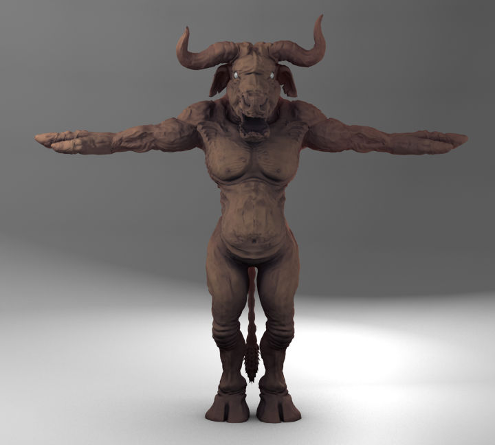
The elephant model used in this post, as well as other realtime models, are available from the RabbitMacht Store to use in your own projects.
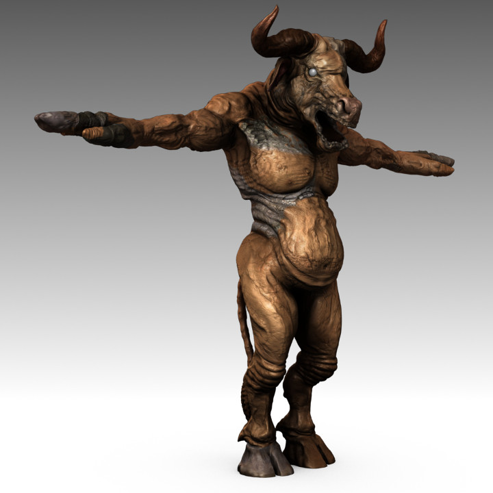
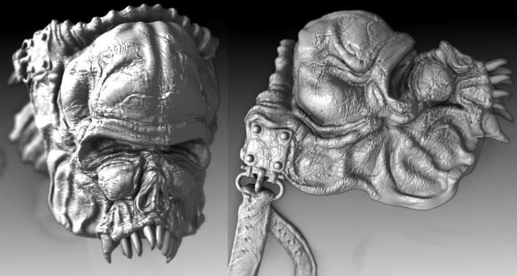
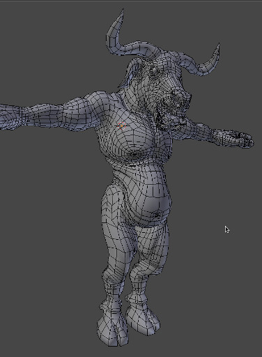
This series of models come with 4K Textures, Non-overlapping UV’s, Normal maps, Rigged and are available in High resolution as well as realtime versions.
- Starting out with Vue : Part 1
 What is a Software Framework A software framework provides a… Read more: Starting out with Vue : Part 1
 - How To Secure Your Site With HTTPS For Free
 Although HTTPS has been a standard web protocol for some… Read more: How To Secure Your Site With HTTPS For Free
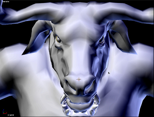
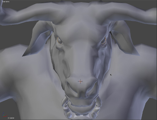
 - A Super Versatile Minotaur, Rigged And Ready To Rumble
 Lets dive into the details on the Minotaur character that… Read more: A Super Versatile Minotaur, Rigged And Ready To Rumble
 - How To Build Game-ready Characters With A Non-destructive Workflow
 When developing 3D characters it’s important to retain as much… Read more: How To Build Game-ready Characters With A Non-destructive Workflow