An Introduction To 3D with Lyndon Daniels
Table of Contents
An Introduction To 3D with Lyndon Daniels
Part 4: Understanding UV’s
UV Layout
 UV’s are used by your 3D application to apply a 2D image to a 3D surface by wrapping the image around the geometric surface.
UV points can be seen and selected from many highend 3D applications from within the viewport but generally cannot be edited from these views. In most cases in order to edit UV’s you need to enter a specific UV texture editor mode.
To begin texture mapping your object we need to create projections that will break our low poly mesh into smaller components called UV shells. These shells will then be sewed together in a manner that best represents the surface we are texture mapping.
iAn important aspect of UV mapping is to create UV’s that do not lie on top of each other (i.e. non-overlapping UV’s) and create a continuous shell that represents our mesh as close as possible.
UV Projections
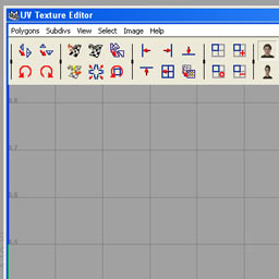
 When first invoking the UV texture editor mode you might notice that your character’s UV look nothing like your model and could also stretch outside of the 0 to 1 UV texture space.
 Most 3D applications represent UV texture space as having two dimensions U and V. the U dimension extends along the horizontal axis of the image and the V direction extends along the vertical axis of the image.
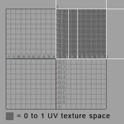
When a texture is assigned to a model the texture will by default appear in the 0 to 1 quadrant of the UV texture editor and uniformly tile from this space horizontally and vertically. In some 3D applications, texture space extending beyond the 0 to 1 boundry might not be visible by default, this is not a problem as we will only be utalizing the default visible texture space of your 3D application for the purposes of this course. In our case we will need to arrange our UV’s on our mesh to fit into the 0 to 1 UV texture space.
 There are many different techniques for laying out a model’s UV’s. Many 3D applications offer primitive UV projections such as Cylinderical mapping, Box mapping or Projection mapping which can suffice as a good starting point when laying out a complex model’s UV’s.
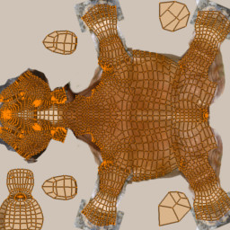
 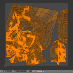 A more advanced method for laying out UV’s would involve generating seams on the model then creating projections from the seamed geometry. The result of this method is that UV Islands are created these islands can then be stitched together in the UV editor or if the seams joining the islands are not going to be visible the islands will generally not be stitched together. This can lead to a less distorted UV layout. Creating Islands can also be achieved in some 3D applications by selecting specific faces of a mesh and creating a projection from those faces.
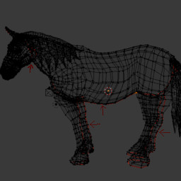
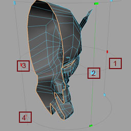
An example of this method can be seen in horse image below where the red lines signify seams on the model. As you can see these seams are carefully placed in areas that are not likely to be visible during rendering and final output. Many 3D applications can also help with hiding seams by allowing the ability to paint out seams on a texture with a clone paint tool.
Download and inspect the UV’s on this horse model for yourself, it’s all totally free!