Posted on Leave a comment

Minotaur V : Form, Tone and Posture

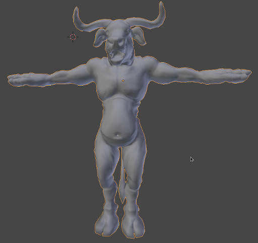
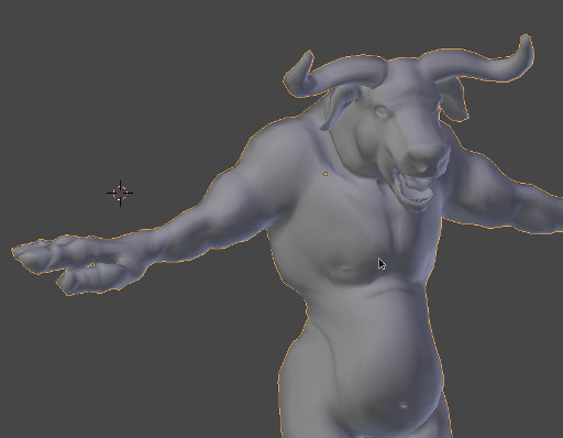
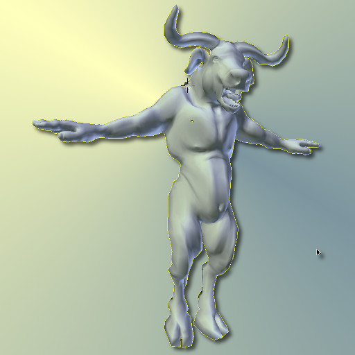
General Form Improvements

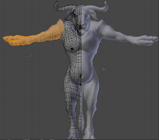
The arms and shoulder area have been in need of some major form adjustments, for example the shoulders are in a position that relates more to the arms being at 45 degree rotations rather than the current almost perpendicular (to the torso) position.

This sort of thing is often a side effect of using a selection with a fall-off also known as a soft selection.

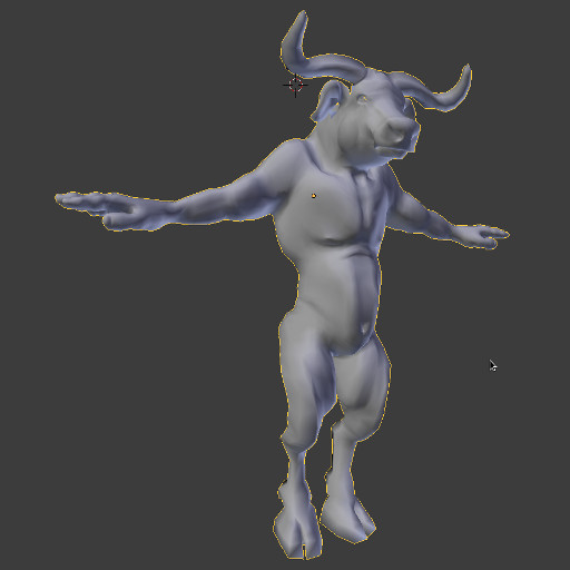
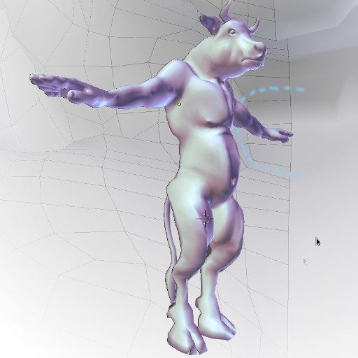
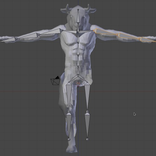
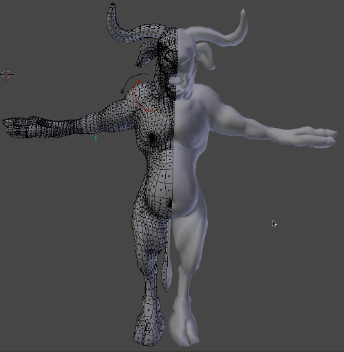
The Black Arrow indicates the first adjustment, the arms are attached too low at the shoulders and need to
be raised.
The Teal Arrow indicates the area that adjustment should not exceed. In other words the area from the elbows down are currently parallel to the ground plane. Although this is not exactly a natural position, it will provide the best position for setting-up the hand’s rig (including the fingers). However it is not necessarily a “better” rest pose than having the characters arms at 45 degrees to the torso. One of the reasons why you might choose to use the latter as a rest pose is because with the arms lowered, in a more relaxed position there will be less deformation in the shoulder area.
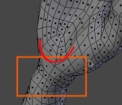
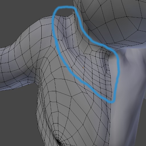
The Red Arrow indicates the direction for a more natural flow of edge loops to make up the topology of the pectorals joining the shoulder area. As you can see the current geometry does not flow in the direction of the arrow and forms too much of a concave join.

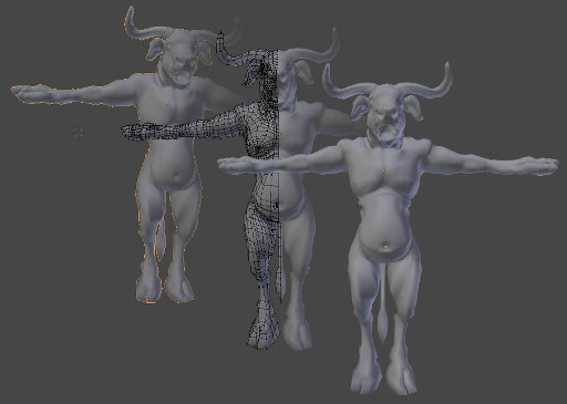
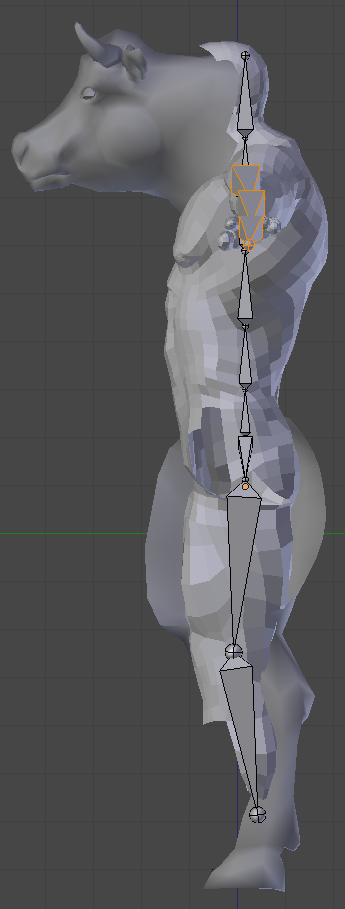
Although the problem could have been fixed by making a selection from the tips of the fingers to the elbow and using a fall-off that extended into the shoulders, I chose instead to use a hard selection due to the side-effect of the soft-selection raising the geometry of the pectorals and torso.

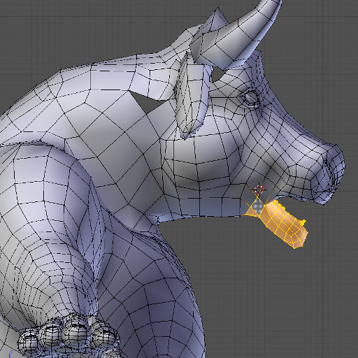
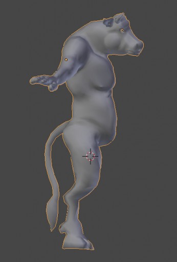
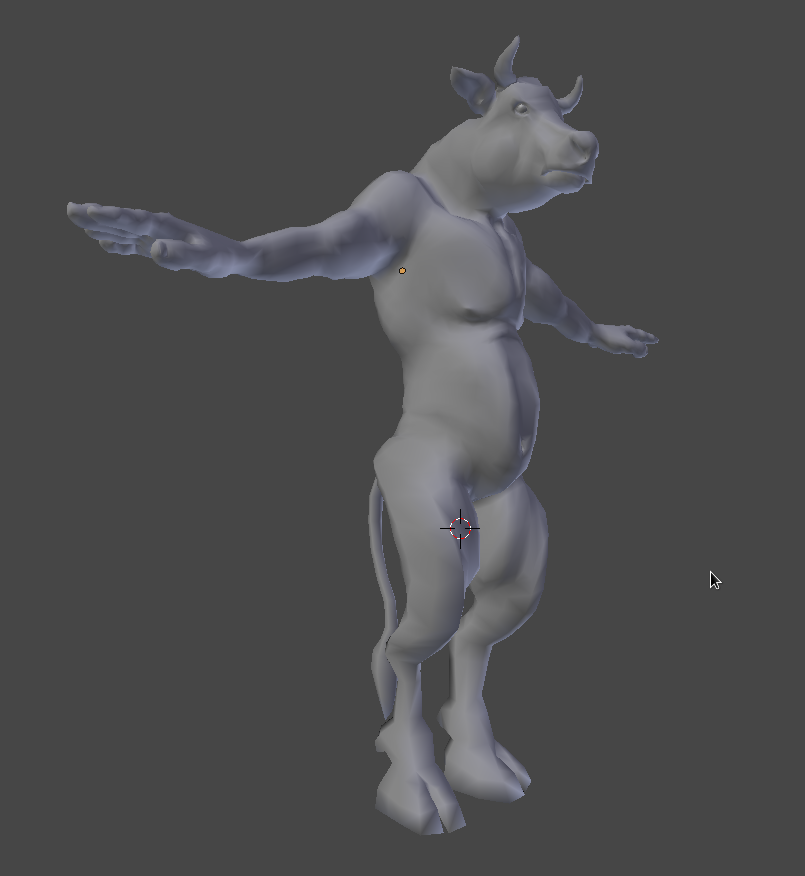
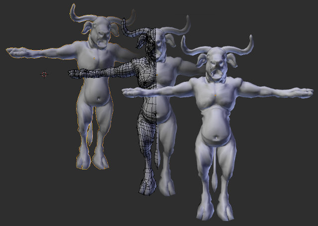
In the above image the arms have been raised to the correct level, the hands are still parallel to the ground plane and the concave area between the pectorals and deltoid (shoulder)has been removed. You might also notice that the shoulders have an exaggerated deformation that emphasize the collar bone, but will be toned down once the pectorals represent a more completed form. With the main problem being that the majority of their surface area is facing sideways instead of towards the front. Pulling the sternum of the chest out from a side viewport with a soft selection will often have this side-effect.

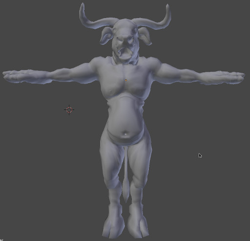
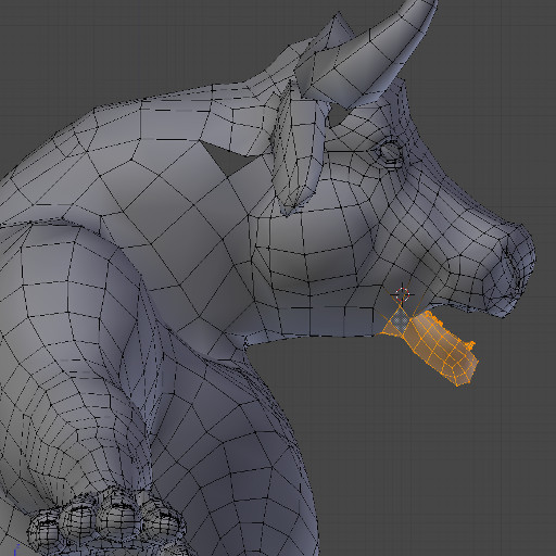
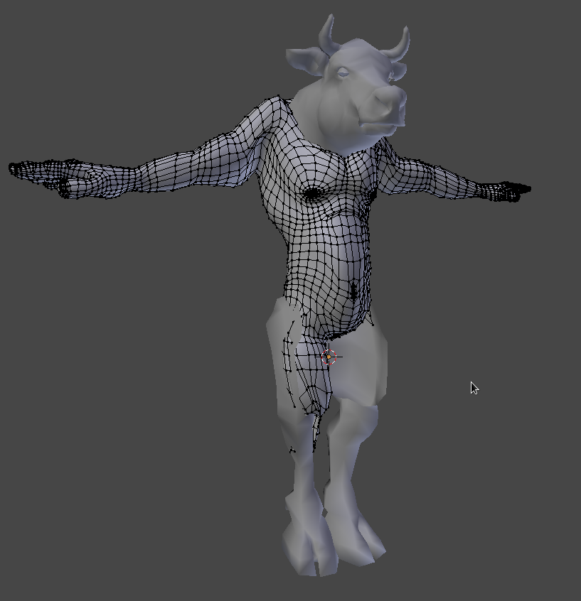
The above image shows the shoulder deformation toned down and the majority of the pectoral’s surface area facing forward.
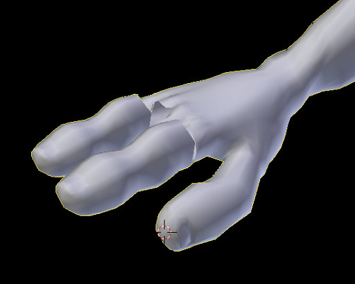
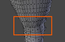
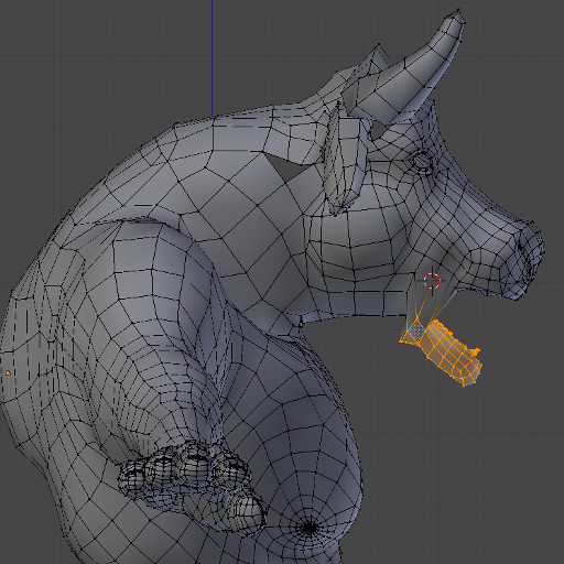
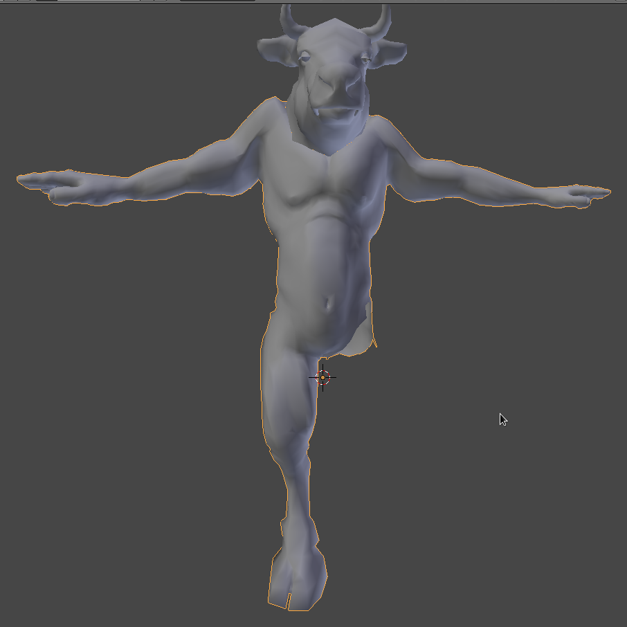
Happy with the results. I move onto the shin and wrists. The main concern is that more volume is needed in both areas.

Posted on Leave a comment

Minotaur IV : Modelling Fingers with Consistent Edge Loops

Hands

The hands of the current Minotaur model inherently have five fingers as they originate from the makeHuman base male model.

However my Minotaur only requires having two main fingers (being part bovine) and a thumb (for the added advantage of being able to hold something such as a weapon). There were two choices that I considered when constructing the fingers.

Option 1: Combine

In an effort to retain the integrity of the models original edge loops, I decided to combine the index with middle finger and ring with pinky finger.

The technique was actually pretty simple, which would involve deleting the interior faces forming the adjacent regions between the two finger pairs.


The merge went along pretty smoothly

As you can see the underside of the fingers stemming from the palm area yielded a relatively workable first attempt and if I’d continued to work with this technique the result would have probably turned out to be equally as effective as option 2.

Option 2: Duplicate

At some point during the combining process I came to the conclusion that it was taking far too much time to correct the geometry on a single finger a process that would have to be repeated on the next finger pair. The combine process left an excess of detail geometry in the palm and not enough in the fingers, which meant that when the surface is subdivided for sculpting I would have had more geometry in the palm than was necessary and not enough in the fingers.

Of course, I could have rectified this by treating the palm as an extension of the fingers and deleting the corresponding rows of palm geometry connected to the deleted finger geometry. This is possible because the edge loops comprising the makeHuman base model are surprisingly well established, as the top of the palm’s extra geometry that is needed to create the fingers originates from the wrist being split into trapezoids which splits a single row of faces into three rows (retaining quadrangles).

This extra amount of detail is particularly necessary to shape the nails of the fingers. The underside of the hand does not require as much detail and employs a different approach that lends itself efficiently to the topology that is required for effective deformation of the palm folding in on itself.

For example, when the thumb raises to touch the pinky finger and usually more importantly (as it tends to be more noticeable in animation) when the hand bends almost perpendicularly about the wrist so that the top of the hand forms an obtuse angle between itself and the wrist and the palm forms an almost acute angle (depending on how double jointed you are) with the underside of the wrist.

The geometry comprising the underside of the hand (including the palm) uses a technique more akin to the “C-shape” technique I used to reduce geometry in the neck area. This is evident when you notice that the topology of the underside of the base mesh’s hand forms a C-shape (see above image). It is these factors that lead me to believe that the combine method would have produced more accurate topology that is more inline with that of the original model’s and potentially alleviating some extensive pushing and pulling of vertices or having to retopologize the base Minotaur model. However, since it meant having to treat the fingers and palm, then reshape them both I decided to go for option 2 the duplicate method which is probably not as accurate in terms of retaining the original edge loops but is certainly much faster to reproduce. Dealing with topology will then be deferred to after the major form issues are addressed.
So having completed a single finger using the combine method, I scrapped the current model and reverted to an old save. I selected a single finger duplicated it, removed it from the model and modified it to have an enlarged nail that resembled something more of a partial hoof.
I then duplicated this finger, scaled it and modified it slightly. I then deleted all the base models fingers and reattached the new fingers, which were already form finished.

I was done in a couple of hours, with only the thumb pending to bring the hand to completion. The edge loops are not as perfect as they would have been with the combine process but I managed to tuck the anomalies between the fingers, an area that will not be visible for the shot I have planned for this model.

It’s really important to find this sort of balance in your own projects, such that you are allocating realistic timeframes to the allocated tasks, and not to be too idealistic in trying to attain perfection. Particularly, when the results of your somewhat extraneous efforts will never be evident.

Posted on Leave a comment

Minotaur III : The Anatomy of a Minotaur’s Mouth

More Form Improvements

extended horns

In the following image I’ve started work on the mouth area. As this character will have a full set of grossly enlarged canines (the Minotaur is after all a devourer of the sons and daughters of Crete), his mouth needs to be modelled in the open position. The previous cow model (from which this minotaur’s head originated) also had a full set of teeth with an interior buckle cavity. However that model was not modelled using the same technique as the Minotaur. The main difference between the techniques is that the cow did not need to have the area surrounding the mouth, including the cheeks, jaw and orbicularis occuli (area surrounding the eye) emphatically stressed. In other words a cow would not open it’s mouth too wide in fact cows can only open their mouths marginally in a vertical direction, the majority of a cows jaw movements are sideways. The Minotaur on the other hand would need to open it’s mouth considerably wider in the vertical direction in order to bear it’s teeth (for intimidation) and also to be able to get a decent grip on it’s prey!
This kind of mouth movement would, over time, cause the area’s mentioned above to become stressed and more pronounced than in that of it’s cow-like brethren. As a result more detail is necessary in the geometry that comprises these areas. It’s therefore best to model the mouth in the stressed position and use a rig to close it, then make improvements to the model’s mouth area in the closed position. The cow’s mouth area was created in the opposite way. The default position/rest was closed and a rig was used to open the mouth and improve the model’s mouth area in the open position (which is less significant for a cow).

You’ll also notice that because the topology of the model needs to be changed in order to add the necessary detail for the mouth area, I’ve also started improving the edge loops in the surrounding areas which will eventually connect to the areas effecting the mouth. This allows me to start thinking about how I’m going to close the edge loops in the most natural way, in other words when the model is deformed by a rig where do I want the skin to fold, crease, stretch etc.
The model’s edge loops form the basis of how the above mentioned deformations appear and in whole
contribute to what many people refer to as the model’s “topology”. Which is a generic term that is used
to describe attributes of all edge loops comprising a model. It’s also worth noting that although the term is often used to describe geometric characteristics of many different types of models it can become a little ambiguous when it is used in the context of a model that deforms to create non-manifold geometry (or geometry with it’s edges not contiguous or connected to other edges). This could simply mean disconnecting the edge of a polygon during the modelling process or any deformation that effectively results in the tearing of a mesh (the physical disconnection of edges, not simply just the appearance of the mesh “tearing”). Although I try to avoid this it is not always practical, particularly when dealing with
edges that will never be seen such as inside the eye sockets and the end of the esophagus. In these cases it might be a preferable solution to leave the edges non-manifold as opposed to increasing the polygon count so as to have a model comprising of perfectly contiguous edges. This is for most 3D artists a personal preference, of which I usually opt for the former, as I prefer keeping my poly count as low as possible. As a result in these posts referring to the model’s topology relates to attributes of the model’s edge loops that are contiguous and not to those edges that will not deform and remain as non-manifold geometry.

Really pushing the mouth to an extreme pose, is better than a neutral position for the rest pose in this
case.

Final rest pose for the mouth
Posted on Leave a comment

Minotaur II : Merging Components without Booleans and Minimizing Polycount

Merging Edges

In this image I’ve merged the head to the main body and here’s a close up of the area that was merged…

The area in blue highlights where the two components were merged. Note that the geometry has not been cleaned, this is a quick merge so that it is easier to visualize the form of the character as a single mesh. The mesh’s topology (the flow of continuous and unbroken lines/edges that form the underlying structure used to calculate the objects deformations) will be cleaned up at a later stage, once I’m happy with the characters general form.
You might also be interested to note the area in the center of the joined pieces where the adam’s apple of the neck and the sternum of the chest lead into each other. In this model there is atleast twice the amount of geometry leading from the sternum of the makeHuman model into the adam’s apple of the cow’s head.


A technique that I often use to reduce the amount of loop cuts needed to join meshes and also prevent creating excessive triangulated polygons is to form C-shaped loops in those areas which (are infact oval shaped loops when the model is merged). This means a reduction of the amount of faces coming in from the higher resolution mesh to the lower resolution mesh by half, as the C-shape of the loop can be used to encompass a row of faces inside it, that would have otherwise resulted in twice the amount of non-manifold edges.

… The following image skips ahead in the progression of images substantially, to demonstrate the
effectiveness of this technique once the geometry was cleaned up. It’s worth noting that the face count
was not increased substantially, nor does the join incorporate triangular polys and the topology of the
mesh flows to create natural edges for deformation.

Here’s a screenshot of what the character looks like as a singular mesh with minimal modifications to the
general form, mainly to scale components to match each others proportions.

Posted on Leave a comment

Minotaur : Planning and Setup

I started a new project a few days ago.

After having a look at my gallery, I decided that none of the images demonstrate my current skill level.
So in an attempt to improve the current state of my gallery I started modelling a Minotaur which will form the main character for a new set of renderings I hope to produce with it. And why did I choose a Minotaur? Well like all good things the idea occurred to me while watching an episode of Scooby Doo!

…and Nick Papas (a visiting art student to the Greek village where the episode was set) who turned out to be the Minotaur, was in fact smuggling rare Art works plundered from the war in barrels filled with olives; which were subsequently set to be shipped to England and sold on the black market. Aha a clue!

My Minotaur is however going to be a little different than that of the Classic 1979 Scooby Doo episode. Since making high quality 3D renderings is a lengthy process, I decided to start posting the progress of the image making process here and also discussing techniques that I use when making 3D characters from start to finish.

Realtime Cow Model

I’d previously made a 3D model of a cow in Blender which I released for free under a CC0 license and can be downloaded at Blendswap.

MakeHuman 3D Modelling Software

I’d also contributed my modelling services to an open source project called MakeHuman which is used to generate various human type 3D models and was still in Pre-Alpha stage at the time

The application has since received many updates that have taken it to an Alpha release and vastly improved models, interface and customizations.
So instead of starting my minotaur base model from scratch I decided to combine my realtime cow model with the makehuman base model. The major issue with using this technique would be creating geometry that has contiguous edge loops, and minimal polygonal triangulation. The makehuman base model is a great example of this type of geometry as it is made up entirely of quadrangles (4 sided polygons). This allows for the most natural (and predictable) topology deformation in humanoid characters. However, it is not always necessary for every humanoid mesh to be made up entirely of quadrangles, depending on what the model will be used for using a combination of quadrangles and strategically placed triangular polygons can contribute to improving your systems performance when rendering a realtime 3D model in your applications OpenGL viewport and at the same time not compromising on the quality of the “look” of your model. The “look” of the model is what the model appears like in the final product and if you have done a good job of modelling it the concepts used in the model’s underlying geometry should be
completely abstracted to the viewer.

Early Days
So to sum it up…

And that is basically what I started with. I then deleted the components of the two models that I did not need trying to preserve as much as I could of the original models, this would effectively reduce the amount of additional modelling I need to do.

MakeHUman base model and cow, uncombined
FK rig for modelling

As you can see from the makeHuman base model I kept the torso, arms and thighs. From the cow model I kept the head and the lower legs.
As certain areas of the mesh needed to be moved and rotated to accommodate for a completely different skeletal structure to that of a human, I decided to create a quick FK (forward kinematics) rig, bind the rig to the combined model and rotate the FK rig into the new default/rest pose for this model then delete the rig applying it’s transforms to the model.

Using this technique for modelling can be far more effective than selecting vertices and transforming them, as the modifier binding the geometry to the rig will help to prevent hard deformations that invariably result in large groups of vertices getting tangled and lost within the negative space composing the model interior. These would then have to be manually moved into new positions. A very time consuming process.

Entire sections of the model can now be transformed into new positions without having to worry too much about intersecting geometry.

Once the main components making up the base mesh have been scaled and moved into place, then joined into a single mesh, the model can be bound to the skeleton and rotated into position using FK. Setting up a proper rig with IK and other controllers would be overkill, it’s also worth noting that the Non Manifold edges of the components that will contribute to the completed base mesh do not need to line up at this
stage (as is demonstrated in the image above). A rough approximation of where the majority of vertices will reside in relation to other vertices from the other mesh components is all that is necessary at this stage. What this means is that accuracy is not the issue nor is determining the direction of continuous flowing geometry, what is important is that the model resembles an approximation of the final output, in
terms of form. Once the various mesh components have been joined together and bound to the temporary rig you can concentrate on the models default or “rest” pose.

In the above image the model has been moved into it’s new rest pose and the skeletal transforms have been baked into the geometry. I chose not to delete the skeleton in the event that I need to move entire limbs or other regions of the model at a later stage in the modelling process once it becomes more evident where the character is most likely suffering from the effects of gravity and mass exerted on his underlying
skeletal structure. This is more to do with the “look” of the model rather than full-filling a specific technical criterion.

Mirror, Mirror on the YZ plane, help me model with speed to gain

As you can see I have not mirrored the model yet (as is visible in the above image) and as a result I’ve only attached one limb to the main torso section. Doing this any more than once is a complete waste of time (in this particular case). So after attaching the limb, and again I’m not interested in continuous edge loops at this stage, I delete half of the model and apply a mirror modifier to the remaining half. Which
will cut the amount of time I need to spend on certain modelling tasks by half.